
Concrete prefabricated floor slab pouring forming device

A technology for concrete and floor slabs, which is applied in the directions of forming surfaces, ceramic forming machines, mold panels, etc., can solve the problems of waste materials, poor concrete fluidity, waste, etc., and achieve the effect of improving the applicability and flexibility of the device, and the adjustment is convenient and quick.

Active Publication Date: 2020-03-17
颍上晶宫绿建节能建筑有限责任公司
View PDF10 Cites 10 Cited by
  • Summary
  • Abstract
  • Description
  • Claims
  • Application Information

AI Technical Summary

Problems solved by technology

The applicant found that when producing concrete prefabricated slabs, it is usually necessary to use boards such as wood to make pouring formwork, so that concrete is injected into the pouring formwork to form a prefabricated floor slab. Since the size of the building requires the same requirements for all parts, the required size of the concrete prefabricated floor slab It is also different. When manufacturing prefabricated slabs, it is necessary to manufacture pouring formwork of different sizes according to demand, and it is time-consuming and labor-intensive to manufacture pouring formwork. It is very wasteful. When pouring at the same time, due to the poor fluidity of some concrete, it is difficult to achieve uniform pouring. It is necessary to manually adjust the pouring pad, and at the same time, it needs to be troweled and leveled, and the pouring efficiency is low.

Method used


Image

  • Concrete prefabricated floor slab pouring forming device
  • Concrete prefabricated floor slab pouring forming device
  • Concrete prefabricated floor slab pouring forming device

Examples


Embodiment Construction

[0034] In order to make the object, technical solution and advantages of the present invention clearer, the present invention will be described in further detail below in conjunction with specific embodiments and with reference to the accompanying drawings.

[0035] It should be noted that all expressions using "first" and "second" in the embodiments of the present invention are to distinguish two entities with the same name but different parameters or parameters that are not the same, see "first" and "second" It is only for the convenience of expression, and should not be construed as a limitation on the embodiments of the present invention, which will not be described one by one in the subsequent embodiments.

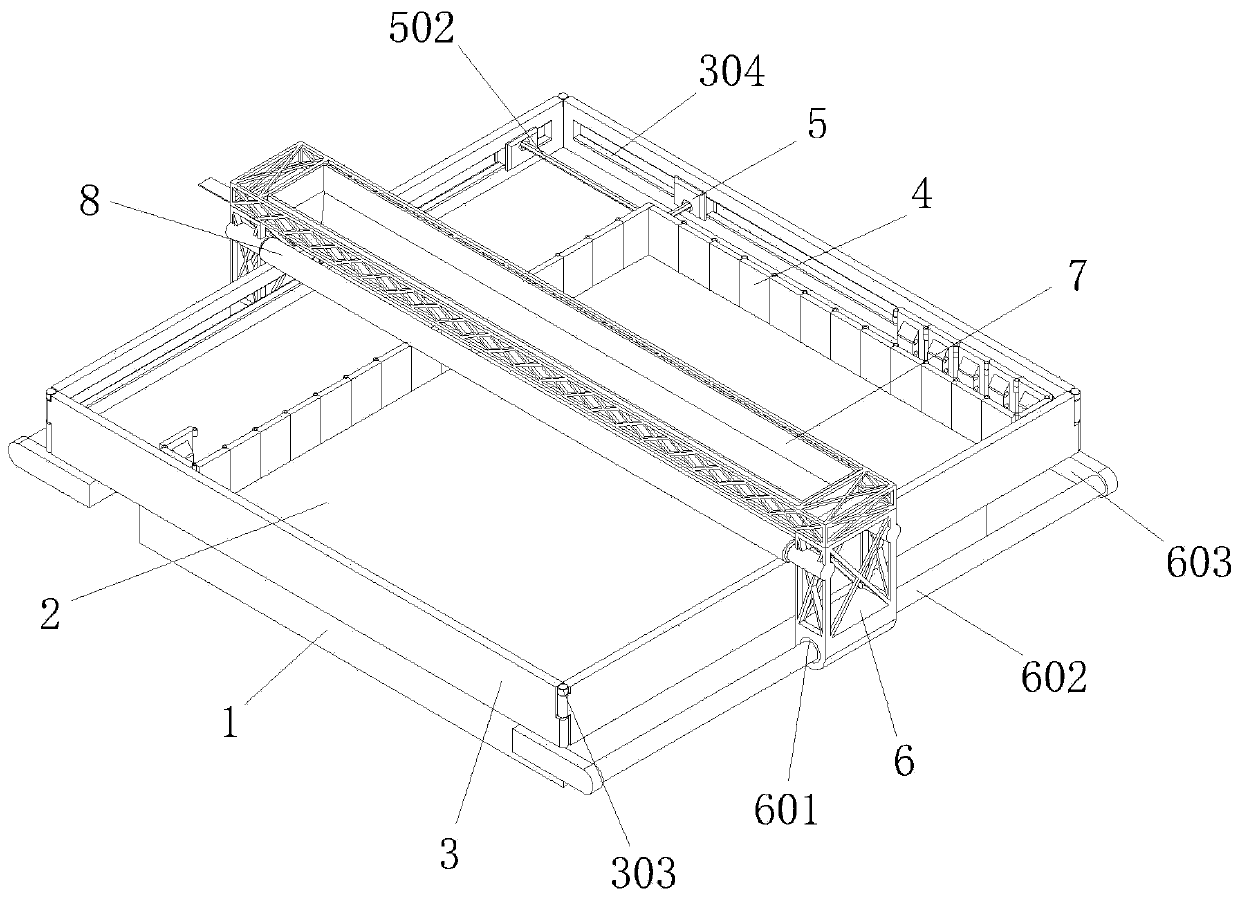
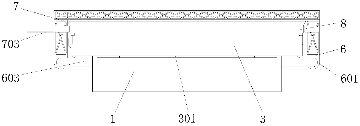
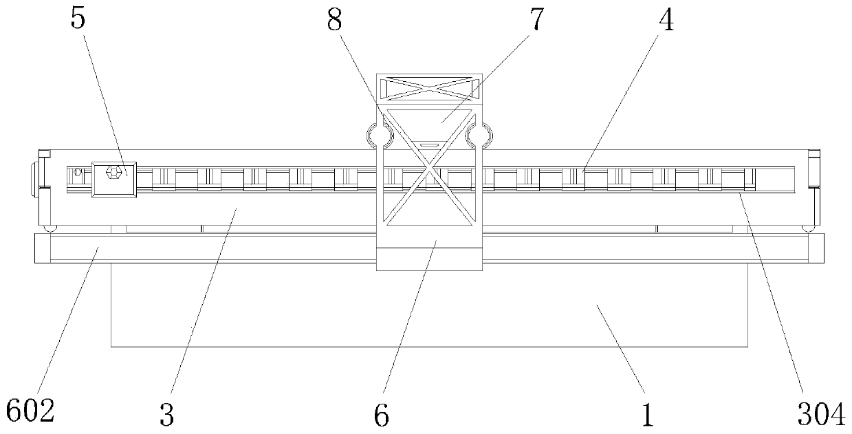
[0036] As an embodiment, a concrete prefabricated floor pouring forming device includes:

[0037] The base 1 is provided with a square bottom plate 2 with a square structure above it;

[0038] The fixed side templates 3 are symmetrically provided with locking holes 3...


PUM


Abstract

The invention discloses a concrete prefabricated floor slab pouring forming device. The concrete prefabricated floor slab pouring forming device comprises a base, fixed side formworks, split side formworks and an adjusting sliding seat, wherein a square bottom plate of a square structure is arranged on the base; the fixed side formworks are rotatably connected to the four edges of the square bottom plate through connecting rotating shafts; the split side formworks are connected into a whole through folding rotating shafts and vertically arranged on the upper surface of the square bottom plate;and a connecting sleeve is arranged in the middle of the adjusting sliding seat, and a hexagonal fixing rod is arranged in the middle of the connecting sleeve in a nested mode. According to the concrete prefabricated floor slab pouring forming device, a prefabricated floor slab pouring formwork is formed through the square bottom plate and the fixed side formworks, the split side formworks arranged on the inner sides of the fixed side formworks are connected into a whole through the folding rotating shafts, the multiple split side formworks are spliced through folding and fixed through the hexagonal fixing rod, thus the sizes of the two side edges of the formwork can be adjusted, the pouring size of a prefabricated floor slab is adjusted accordingly, adjusting is convenient and rapid, andthe applicability and using flexibility of the device are improved advantageously.

Description

technical field [0001] The invention relates to concrete prefabricated floor slab manufacturing equipment, in particular to a concrete prefabricated floor pouring forming device. Background technique [0002] Concrete prefabricated slabs are generally processed and produced in factories through standardized and mechanized methods, while traditional cast-in-place concrete requires on-site mold making, on-site pouring and on-site maintenance, which takes a long time and is low in efficiency. The applicant found that when producing concrete prefabricated slabs, it is usually necessary to use boards such as wood to make pouring formwork, so that concrete is injected into the pouring formwork to form a prefabricated floor slab. Since the size of the building requires the same requirements for all parts, the required size of the concrete prefabricated floor slab It is also different. When manufacturing prefabricated slabs, it is necessary to manufacture pouring formwork of differe...

Claims


Application Information

Patent Timeline
IPC IPC(8): B28B7/02B28B7/00B28B23/02
CPCB28B7/0002B28B7/0011B28B7/0032B28B7/0055B28B7/02B28B23/02
Inventor 王晗
Owner 颍上晶宫绿建节能建筑有限责任公司
Learn More