Electric heating type supersonic ejector experiment system

An experimental system, electric heating technology, applied in control/regulation systems, temperature control using electric means, instruments, etc., can solve problems such as limited experimental time, increased experimental risk factor, difficulty in adjusting total temperature and total pressure, etc. , to achieve the effect of high safety factor

Inactive Publication Date: 2020-03-17
NAT UNIV OF DEFENSE TECH
9 Cites 1 Cited by

AI-Extracted Technical Summary

Problems solved by technology

[0004] At present, some scholars at home and abroad have conducted a lot of research on high total temperature ejectors, but they all use gas generators to generate primary flow. Although this can generate high total temperature and total pressure primary flow, it is limited by the gas generator Working characteristics, the adjustment of its ...

Method used

[0028] The electric heater 2 is provided with an incoming temperature control box for controlling the heating temperature of the electric heater. The heating temperature of the inc...

Abstract

The invention provides an electric heating type supersonic ejector experiment system. An air source is connected with an electric heater through an air path; incoming flow air from the air source is inputted into the electric heater for heating through an air path; the output pipeline of the electric heater is communicated with the inlet end of a supersonic nozzle, the outlet end of the supersonicnozzle is connected with an ejector sleeve, and gas heated and outputted by the electric heater is accelerated by the supersonic nozzle and then enters the ejector sleeve as primary flow to suck secondary flow. The electric heater preheating mode is adopted, the experiment safety is guaranteed, experiment parameters are easy to adjust and data acquisition and analysis are facilitated.

Application Domain

Temperature control using plurality of sensorsStructural/machines measurement +1

Technology Topic

Electric heatingEngineering +4

Image

  • Electric heating type supersonic ejector experiment system

Examples

  • Experimental program(1)

Example Embodiment

[0022] The technical solutions in the embodiments of the present invention will be clearly and completely described below with reference to the accompanying drawings in the embodiments of the present invention. Obviously, the described embodiments are only some, but not all, embodiments of the present invention. Based on the embodiments of the present invention, all other embodiments obtained by those of ordinary skill in the art without creative efforts shall fall within the protection scope of the present invention.
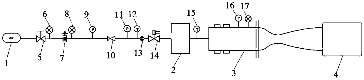
[0023] refer to figure 1 , is a schematic structural diagram of Embodiment 1 of the present invention.
[0024] An electrically heated supersonic ejector experimental system, comprising an air source 1 connected to an electric heater 2 through an air circuit, the incoming air from the air source 1 being input to the electric heater 2 for heating through the air circuit, and the electric heater The output pipeline of 2 is connected to the inlet end of the supersonic nozzle 3, and the outlet end of the supersonic nozzle 3 is connected to the ejector sleeve 4. The gas heated and output by the electric heater 2 is accelerated by the supersonic nozzle 3 and then enters the ejector sleeve as a primary flow. Cartridge 4, which performs suction on the secondary flow. In order to facilitate the replacement of the supersonic nozzle 3 , the supersonic nozzle 3 is detachably connected to the output pipeline of the electric heater 2 . The ejector sleeve 4 is detachably connected to the output end of the supersonic nozzle 3 .
[0025] A stop valve 5, a first pressure gauge 6, a pressure reducer 7, a second pressure gauge 8, a first pressure sensor 9, and a flow regulating valve are sequentially arranged on the air path between the air source 1 and the electric heater 2. 10 . The second pressure sensor 11 , the first temperature sensor 12 , the turbine flowmeter 13 and the pneumatic valve 14 . The cut-off valve 5 may be a manual cut-off valve. The first pressure gauge 6 monitors the air pressure output by the air source 1 . The pressure reducer 7 regulates the air pressure. The second pressure gauge 8 monitors the gas path pressure after the pressure adjustment of the pressurizer. The flow regulating valve 10 realizes the regulation and control of the flow of the incoming air in the air passage. Each pressure sensor, temperature sensor and turbine flowmeter respectively collects pressure, temperature and flow information at corresponding positions.
[0026] The output pipeline of the electric heater 2 is provided with a second temperature sensor 15 for monitoring the temperature of the air output from the electric heater. The outlet end of the supersonic nozzle 3 is provided with a third temperature sensor 16 and a third pressure gauge 17 .
[0027] The air source 1 is a gas storage tank storing air, and the incoming air with the upstream pressure of 10 MPa output by the air source 1 is transmitted to the gas inlet of the electric heater 2 through the air path. Among them, the pressure regulating device and the flow regulating device on the gas circuit adjust and control the pressure and flow of the incoming air, and at the same time, there are pressure gauges, pressure sensors, flow sensors, and temperature sensors on the gas circuit to adjust the pressure at different positions on the gas circuit, Real-time detection of flow and temperature.
[0028] The electric heater 2 is provided with an incoming temperature control box for controlling the heating temperature of the electric heater. The heating temperature of the incoming air in the electric heater is controlled by the incoming air temperature control box, and the electric heater rapidly heats the incoming air to increase its total temperature.
[0029] The heated gas is accelerated (eg, accelerated to Ma2.25) through the supersonic nozzle 3 and then enters the ejector sleeve 4 as a primary flow to perform suction on the secondary flow, thereby completing the experiment.
[0030] In one embodiment: the maximum power of the electric heater is 30kW, the designed air flow is 50-100g, the heating temperature is 470K-520K, the main flow pipeline, the pipe diameter is DN20, the supply air flow is 50-150g/s, and the loss along the way is about 0.2MPa.
[0031] The ejector sleeve 4 is detachably connected to the output end of the supersonic nozzle. In this way, the ejector sleeve 4 can be easily replaced according to the needs of the specific problem. In order to quantify the parameters of the primary flow conveniently, a temperature sensor and a pressure sensor are arranged at the outlet end of the supersonic nozzle. The temperature sensor uses a thermocouple probe to measure the temperature of the incoming flow, and transmits the signal to the electric heater temperature control box in real time. The latter adjusts the working power of the heater according to the temperature signal, and stops heating when the experimental set temperature value is reached.
[0032] In summary, although the present invention has been disclosed above with preferred embodiments, it is not intended to limit the present invention. Any person of ordinary skill in the art, without departing from the spirit and scope of the present invention, can make various modifications. Therefore, the protection scope of the present invention shall be subject to the scope defined by the claims.

PUM

no PUM

Description & Claims & Application Information

We can also present the details of the Description, Claims and Application information to help users get a comprehensive understanding of the technical details of the patent, such as background art, summary of invention, brief description of drawings, description of embodiments, and other original content. On the other hand, users can also determine the specific scope of protection of the technology through the list of claims; as well as understand the changes in the life cycle of the technology with the presentation of the patent timeline. Login to view more.

Similar technology patents

A layering and partially filling coal mining method of thick seams

InactiveCN104832178Aimprove securityLower filling costs
Owner:CHINA UNIV OF MINING & TECH

Nano metal silver antibiotic paint and its preparing method

InactiveCN1616559Aimprove security
Owner:RESEARCH INSTITUTE OF TSINGHUA UNIVERSITY IN SHENZHEN

Cloud data security protection method

InactiveCN104767745Aimprove securitySolve user privacy leakage
Owner:INSPUR GROUP CO LTD

Classification and recommendation of technical efficacy words

  • improve security

Pesticide micro-capsule granules and preparation method thereof

InactiveCN102100229Alow toxicityimprove security
Owner:联合国南通农药剂型开发中心 +1

Method for achieving user authentication by utilizing camera

InactiveCN103678984Aimprove securityGuaranteed picture quality
Owner:湖北微模式科技发展有限公司
Why Eureka
Try Eureka