Ribbon binding device

A technology of binding device and binding seat, which is applied in the direction of cable installation device, cable installation, electrical components, etc., can solve problems such as troubles, and achieve the effect of convenient use, good binding effect and convenient binding

Inactive Publication Date: 2020-03-17
TAIZHOU CITY DADI LIGHT DECORATIONS
View PDF6 Cites 0 Cited by
  • Summary
  • Abstract
  • Description
  • Claims
  • Application Information

AI Technical Summary

Problems solved by technology

[0003] During the production of lighting decorations, it is usually necessary to bind the wires to the poles of the lighting decorations. In the existing production, plastic cable ties are usually used to bind the wires and the poles. Pull the toothed belt to tighten after aligning the tooth holes, but the operator needs to hold the wire and the pole while operating the binding, which is generally troublesome. It is imminent to study a cable tie binding device

Method used


Image

  • Ribbon binding device
  • Ribbon binding device
  • Ribbon binding device

Examples


Embodiment

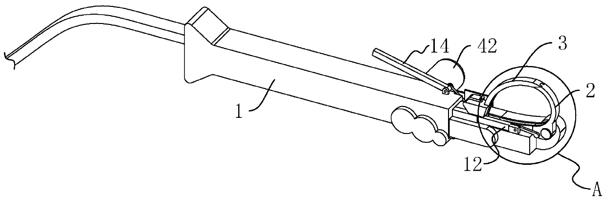
[0048] A cable tie binding device, such as figure 2 , Figure 4 As shown, it includes a binding seat 1 , a binding arm 2 , a guiding arm 3 , a tightening assembly 4 and a cutting assembly 5 .

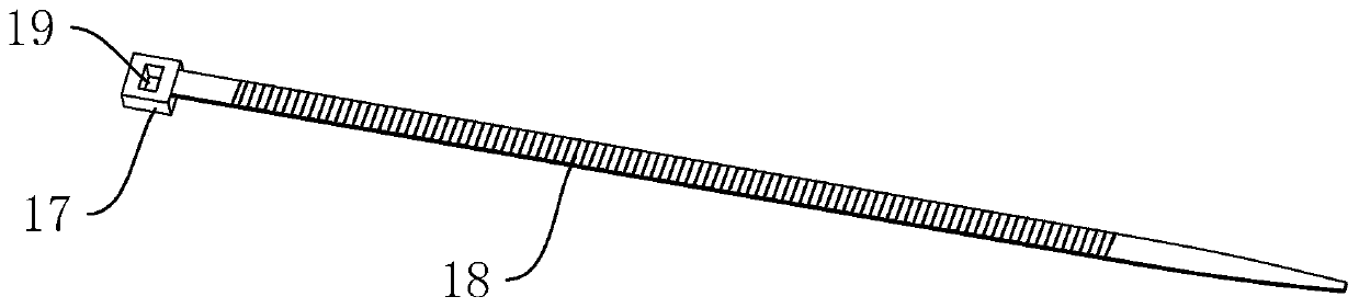
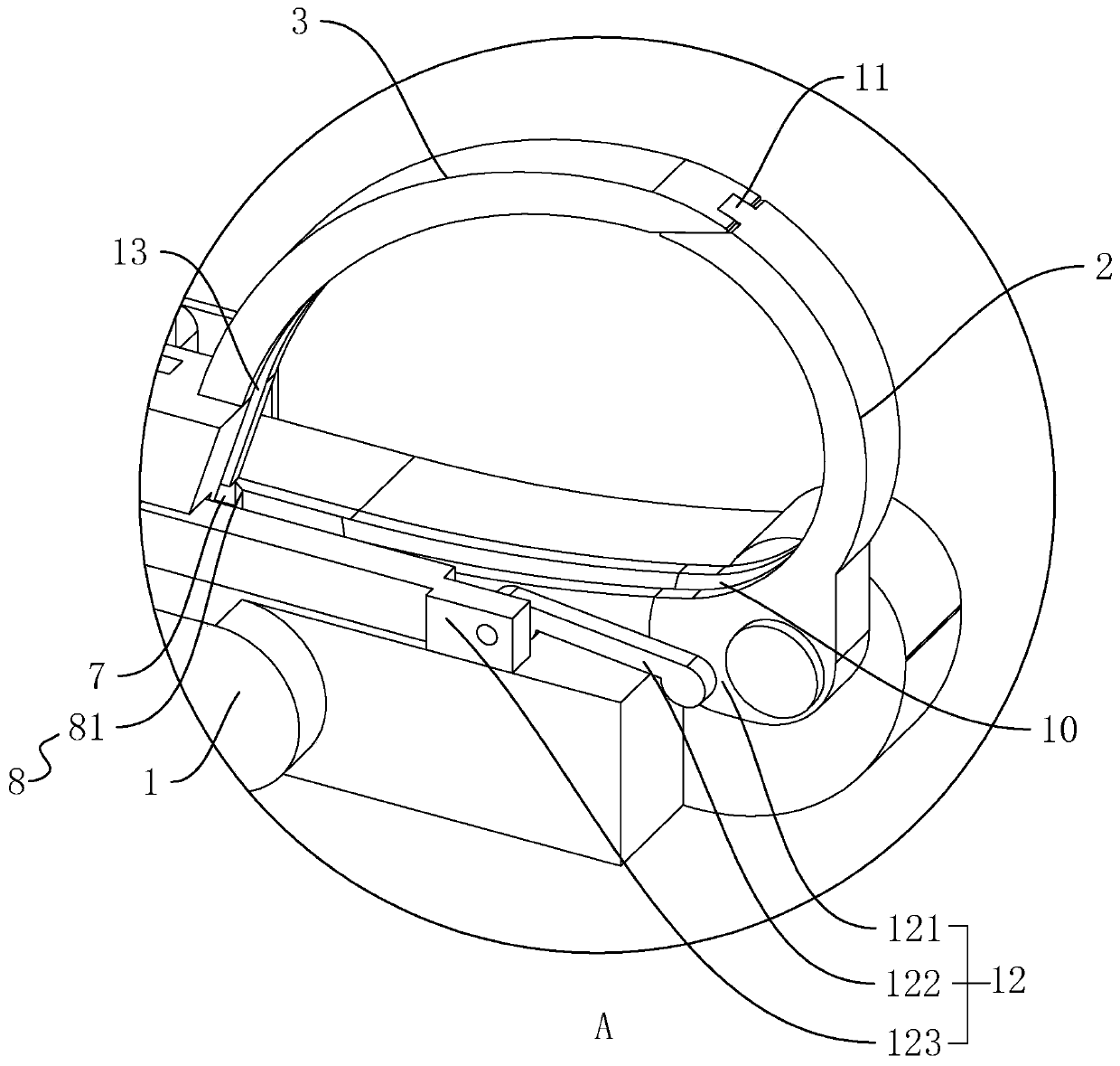
[0049] like image 3 , Figure 4 As shown, the binding seat 1 is provided with a feed channel 6 along the length direction. The feed channel 6 has a square cross-section and is set corresponding to the strap head 17 of the strap. The feed channel 6 is used to limit the rotation of the strap. One end of the feeding passage 6 is connected with a feeding groove 7 , and the feeding groove 7 is set on the binding seat 1 . The feed trough 7 is provided with a limiter 8 near the feed channel 6, the limiter 8 is two limit blocks 81 fixedly connected to the side wall of the feed trough 7, and a tooth is provided between the two limit blocks 81. There is a gap through which the belt 18 passes, and the side wall of each limiting block 81 close to the feed channel 6 is set at an obtuse angle t...


PUM


Abstract

The invention discloses a ribbon binding device, and relates to the field of binding equipment. The ribbon binding device comprises a binding seat, a binding arm, a guide arm and a tightening assembly, a feeding channel is formed on the bundling base, and one end of the feeding channel communicates with a feeding groove. The feeding groove is formed on the bundling base, a through hole is formed in the feeding groove and is located at the side, close to the feeding channel, of a limiting part, and the tightening assembly is located at one end of the through hole away from the positioning groove. The bundling arm is hinged to the end, corresponding to the feeding groove, of the bundling base, and a guide groove communicating with the feeding groove is formed on the bundling arm. The guide arm is arranged on the bundling base, a guide groove is further formed on the guide arm, a groove opening, close to the feeding groove, of the guide groove is aligned at the through hole, and the feeding groove, the guide groove and the guide groove are spliced to form a ring shape. By arranging the binding base, the binding arm, the guide arm and the tightening assembly, when a binding tape is bound, the binding of the binding tape can be completed only by putting a supporting rod and a wire into the feeding groove, the guide groove and the guide groove to be spliced into the ring shape, and the binding of the binding tape is more convenient.

Description

technical field [0001] The invention relates to the field of binding equipment, more specifically, it relates to a binding device for binding ties. Background technique [0002] Cable ties, also known as cable ties, cable ties, and lock ties, are belts used to tie things together. Most of the market is plastic cable ties, such as figure 1 As shown, its specific structure includes a belt head 17, a toothed belt 18 connected to the belt head 17, the width of both sides of the belt head 17 is larger than the width of the toothed belt 18, and the belt head 17 is provided with teeth for inserting the toothed belt 18 and restricting disengagement. Hole 19. [0003] During the production of lighting decorations, it is usually necessary to bind the wires to the poles of the lighting decorations. In the existing production, plastic cable ties are usually used to bind the wires and the poles. Pull the toothed belt to tighten after aligning the tooth holes, but the operator needs to...

Claims


Application Information

Patent Timeline
Patent Type & Authority Applications(China)
IPC IPC(8): H02G1/00
CPCH02G1/00
Inventor 陶沿蓉
Owner TAIZHOU CITY DADI LIGHT DECORATIONS
Why Eureka
Try Eureka