Eureka AIR delivers breakthrough ideas for toughest innovation challenges, trusted by R&D personnel around the world.

Health monitoring system

A monitoring system and health technology, applied in the direction of measuring devices, testing of mechanical components, testing of machine/structural components, etc.

Active Publication Date: 2020-03-20
AB SKF
View PDF13 Cites 0 Cited by
  • Summary
  • Abstract
  • Description
  • Claims
  • Application Information

AI Technical Summary

Problems solved by technology

This still has room for improvement

Method used


Image

  • Health monitoring system
  • Health monitoring system
  • Health monitoring system

Examples


Embodiment Construction

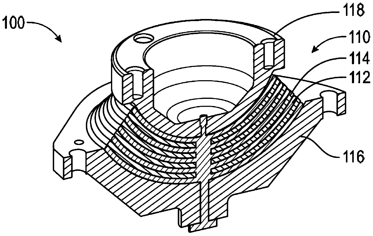
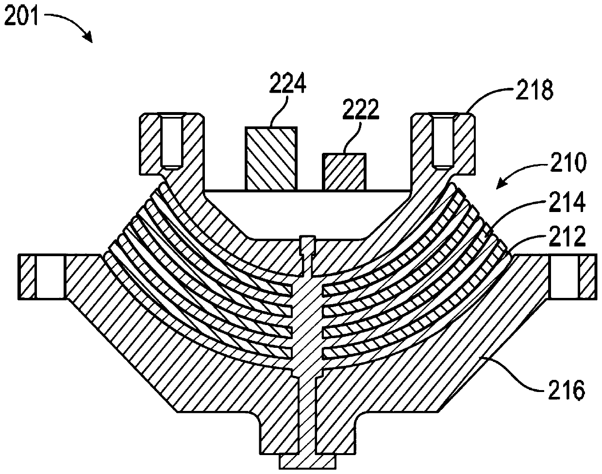
[0077] In order to illustrate the method and apparatus according to the present invention, it will now be combined Figure 1 to Figure 6 Describe some examples of its use.

[0078] figure 1 An example of a laminated elastomeric bearing 100 is shown. Suitably, the laminated elastic bearing 100 may be used to hold and articulate the blade to the hub of a rotor for a rotary-wing aircraft. The elastic bearing 100 includes a laminated elastic unit 110 which is essentially a stack of an elastic body 112 and a rigid strength member 114 in the form of a spherical cap. The elastic unit 110 is disposed between the inner interface member 116 and the outer interface member 118 . Due to the laminated elastic elements, the interface members 116 , 118 are able to twist and bend relative to each other, stressing the elastomeric body 112 . In this example, the outer interface member 118 is a radial support fixed to the hub, where outer is relative to the axis of the rotor, and the inner in...


PUM


Abstract

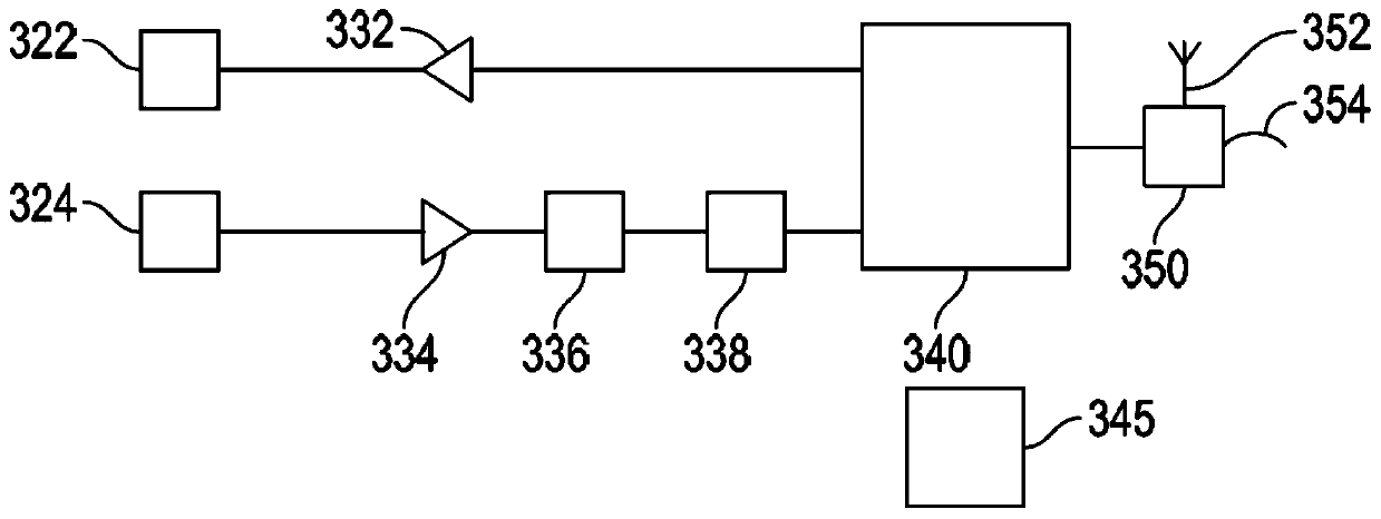
A health and condition monitoring system of an elastomeric component comprising an actuator, a sensor, and a processing unit. The sensor and the actuator need to be attached directly or indirectly tothe elastomeric component. The actuator induces an impulse, or possibly a chirp, into the elastomeric component. The sensor senses the response, the impulse response function. The processing unit analyzes the impulse response function and determines a health and condition indicator. This is repeated and when enough indicators have been determined, then a health and condition marker can be determined, covering if the elastomeric component is in a start period of usage, in a main usage period or in a final period of usage.

Description

technical field [0001] The present invention relates to elastomeric components such as bearings and dampers, and more particularly to monitoring the condition of laminated elastomeric bearings used in rotorcraft. Background technique [0002] The laminated elastic bearing includes a laminated elastic unit and an interface member attached to the laminated elastic unit. A laminated elastic unit includes alternating elastomeric and rigid layers (such as metal layers) that are vulcanized together during the molding process. In most cases the interface member is also part of the forming process and is thus vulcanized together with the laminated elastic unit. The geometry of the various layers of the elastomeric bearing as well as the interface member can vary depending on the application. [0003] For example, elastic bearings are used in rotorcraft such as helicopters. The stiffness of elastomeric bearings undergoes changes with use, age and environmental conditions. The ela...

Claims


Application Information

Patent Timeline
IPC IPC(8): F16C41/00F16C27/00G01M13/00G01M13/045
CPCF16C41/00F16C27/00F16C41/004G01M13/00G01M13/045F16C2233/00F16C2326/43
Inventor 安东尼·C·玻姆阿伦·梅农
Owner AB SKF
Why Eureka
Eureka Blog
Learn More