
Device for monitoring state of power transmission line tower-line system

A technology for a condition monitoring device and a transmission line tower, which is applied to measurement devices, uses optical devices, measures heat, etc., can solve the problems of power supply and equipment reliability of monitoring devices, problems of power supply of communication base stations, and obstacles to large-scale promotion and application, etc. problems, to achieve the effect of meeting harsh environmental conditions, long measurement distance, and reliable work for a long time

Inactive Publication Date: 2011-05-04
SICHUAN HUIYUAN OPTICAL COMM CO LTD
View PDF6 Cites 121 Cited by
  • Summary
  • Abstract
  • Description
  • Claims
  • Application Information

AI Technical Summary

Problems solved by technology

The communication infrastructure in these areas is backward, and there may be problems with the power supply of communication base stations when ice and snow disasters occur
[0013] 3) The power supply of the monitoring device and the reliability of the equipment
[0014] 4) The monitoring system built with the above technologies has the disadvantage of high cost, which creates obstacles for large-scale popularization and application

Method used

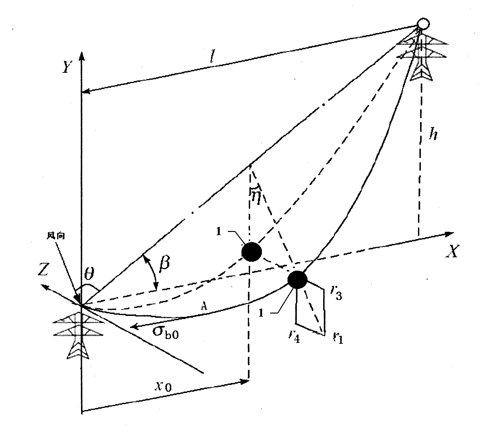
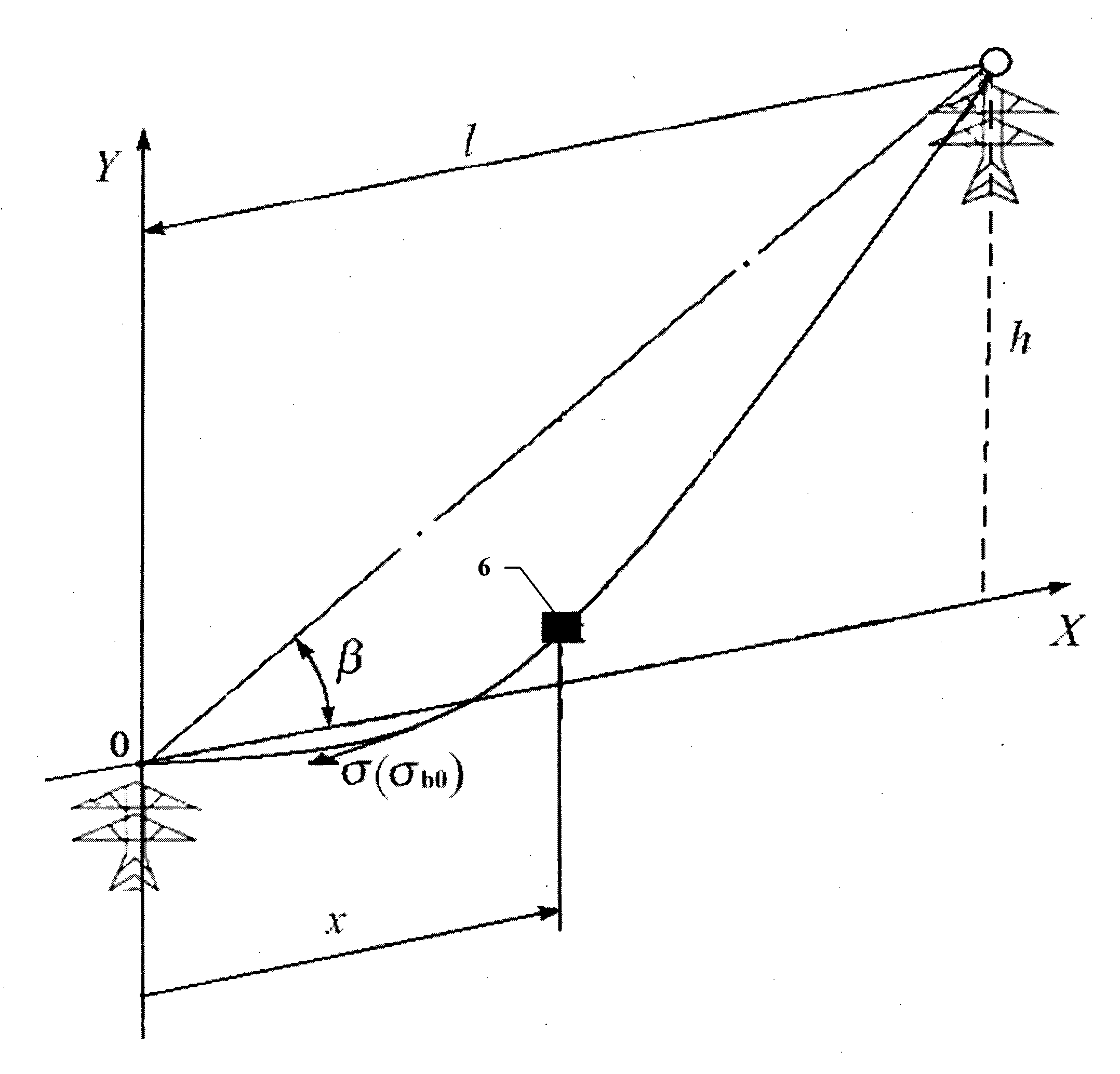

Image

  • Device for monitoring state of power transmission line tower-line system
  • Device for monitoring state of power transmission line tower-line system
  • Device for monitoring state of power transmission line tower-line system

Examples


Embodiment Construction

[0032] Specific embodiments of the present invention will be described below in conjunction with the accompanying drawings, so that those skilled in the art can better understand the present invention. It should be noted that in the following description, when detailed descriptions of known functions and designs may dilute the main content of the present invention, these descriptions will be omitted here.

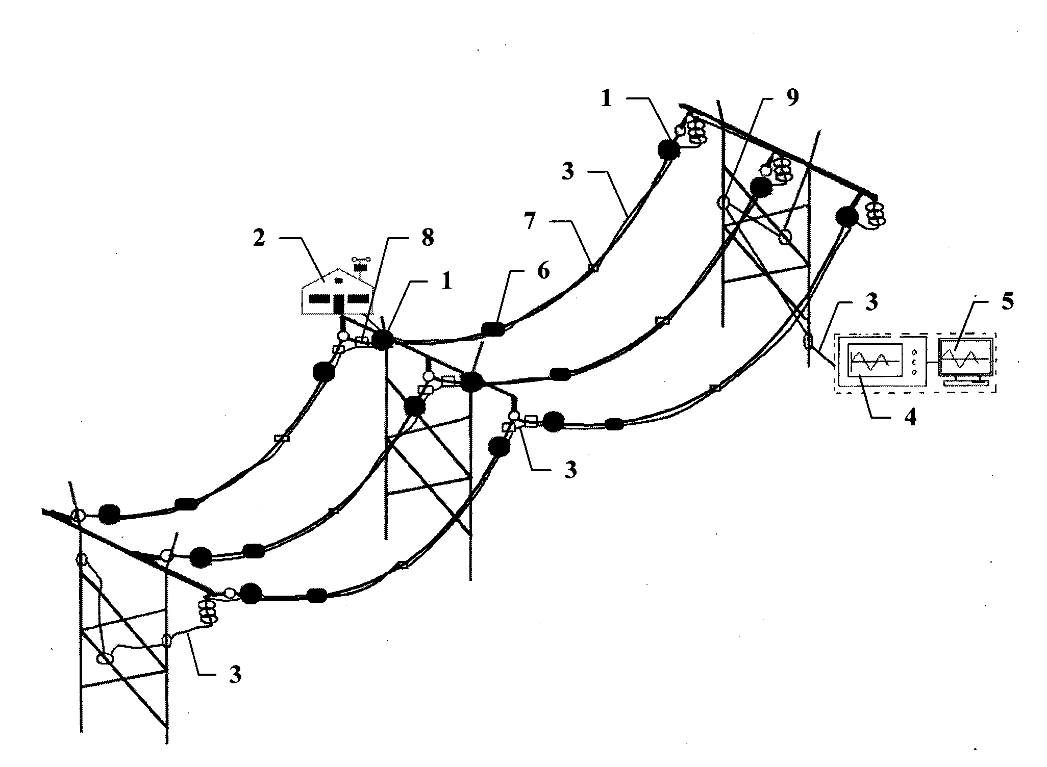
[0033] figure 1 It is a structural schematic diagram of a specific embodiment of the state monitoring device for the transmission line tower line system of the present invention.

[0034] 1. Monitoring of icing quality of transmission wires

[0035] Such as figure 1 As shown, in this embodiment, the state monitoring device for the transmission line tower line system includes two optical fiber strain and temperature sensors for measuring the quality of ice coating in one span, and a pair of optical fiber temperature sensors for optical fiber strain and temperature sensors....


PUM


Abstract

The invention discloses a device for monitoring the state of a power transmission line tower-line system, which fully utilizes the advantages of corrosion resistance, wide operation temperature range, anti-electromagnetic interference, passivity, long measuring distance, reliable operation and long service life and the like of optical fiber sensors to configure the optical fiber sensors on a transmission conductor and a tower in a quasi-distributed structure for detecting the temperature, the strain and the acceleration of the transmission conductor and the multipoint stress variation on the tower which are transmitted to an optical modulator demodulator for demodulating and are sent to a computer analyzing and processing system for calculating to obtain the icing quality, the waving amplitude, the breeze vibration amplitude and frequency and the sag of the transmission conductor, and the inclination angle of the tower, thus realizing the simultaneous monitoring on the icing, the waving, the breeze vibration and the sag of the transmission conductor, and the inclination angle state of the tower, and being capable of finishing long-time reliable operation under the on-site severe environment conditions.

Description

technical field [0001] The invention belongs to the technical field of state monitoring of power transmission line tower line system, and more specifically relates to a device for monitoring the state of icing, galloping, breeze vibration, sag and tower tilt of power transmission line. Background technique [0002] The icing, galloping, breeze vibration, sag and tilting state of the transmission line (hereinafter collectively referred to as the state of the tower line system) may cause phase-to-phase flashover of the transmission line, damage the ground wire, trip and power outage, or even break the tower, resulting in huge damage. Economic loss and serious social impact. [0003] Icing of transmission wires may lead to overload accidents of transmission lines, uneven icing or deicing accidents at different periods, and dancing of iced wires, which may lead to mechanical accidents such as hardware damage, wire breakage, tower damage, insulator string overturning, and crackin...

Claims


Application Information

Patent Timeline
IPC IPC(8): G01K11/32G01B11/16G01P15/00G01L1/24G01W1/02G01C9/00
Inventor 张昌华曹永兴黄琦易建波王恒松
Owner SICHUAN HUIYUAN OPTICAL COMM CO LTD
Learn More