
Infrared emission angle adjustment structure, infrared emission module and remote control apparatus

A technology of infrared emission and structure adjustment, applied in the field of remote control, can solve the problems of excessive infrared emission half-angle, misoperation, etc., and achieve the effect of avoiding misoperation

Inactive Publication Date: 2020-03-20
SZ DJI TECH CO LTD
View PDF20 Cites 0 Cited by
  • Summary
  • Abstract
  • Description
  • Claims
  • Application Information

AI Technical Summary

Problems solved by technology

[0004] In order to solve the above problems, the embodiment of the present invention provides an infrared emission angle adjustment structure, which is used to solve the problem that the emission half-angle of the infrared rays emitted by the existing infrared emission module is too large, and it is easy to cause misoperation in the scene that requires collimation control.

Method used


Image

  • Infrared emission angle adjustment structure, infrared emission module and remote control apparatus
  • Infrared emission angle adjustment structure, infrared emission module and remote control apparatus
  • Infrared emission angle adjustment structure, infrared emission module and remote control apparatus

Examples


Embodiment Construction

[0053] Unless otherwise defined, all technical and scientific terms used herein have the same meaning as commonly understood by those skilled in the technical field of the embodiments of the present invention; the terms used in the description of the embodiments of the present invention herein are for description only The purpose of the specific embodiment is not intended to limit the embodiment of the present invention; the terms "comprising" and "having" in the description and claims of the embodiment of the present invention and the description of the above drawings, as well as any variations thereof, are intended to cover non-exclusive inclusion. The terms "first" and "second" in the description and claims of the embodiments of the present invention or the above drawings are used to distinguish different objects, rather than to describe a specific order.

[0054] Reference herein to an "embodiment" means that a particular feature, structure, or characteristic described in ...


PUM


Abstract

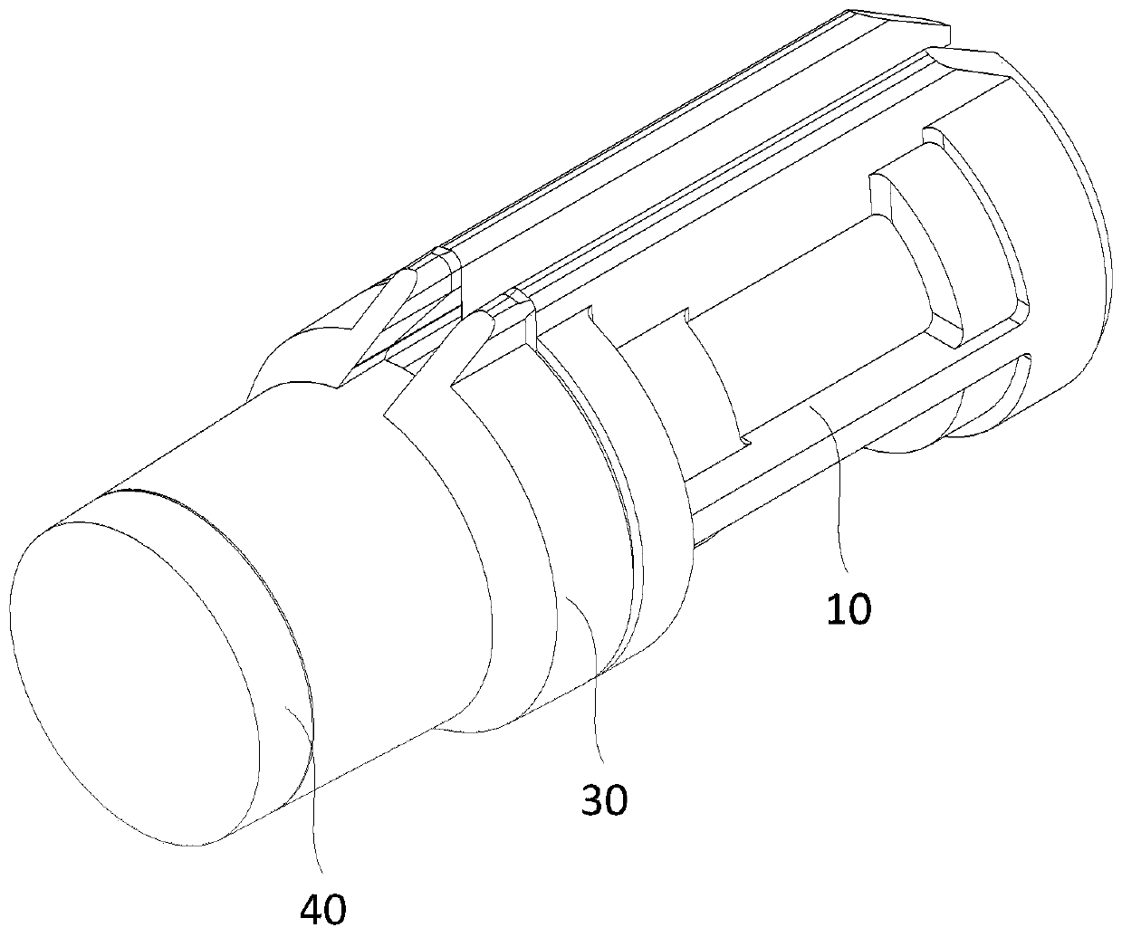
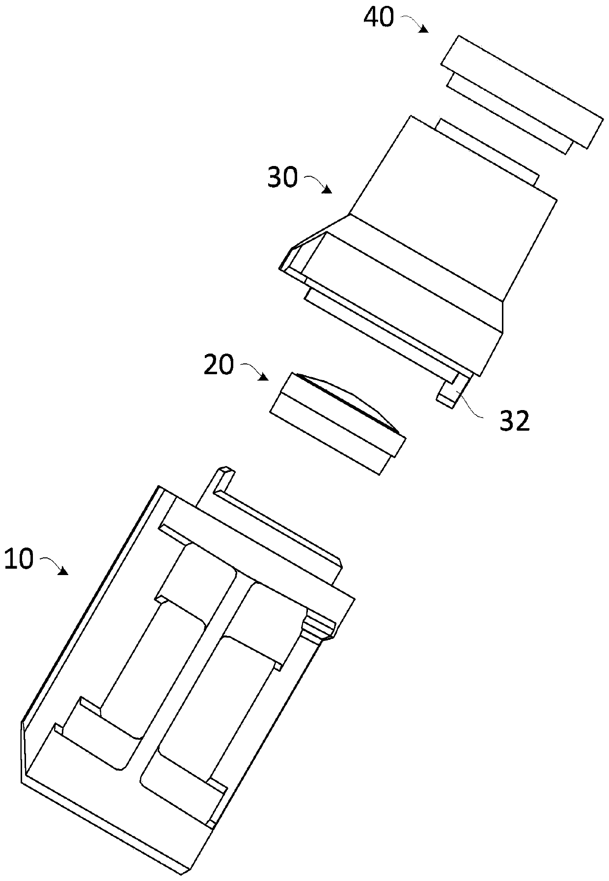
The present application relates to an infrared emission angle adjustment structure, an infrared emission module using the infrared emission angle adjustment structure, and a remote control apparatus.The infrared emission module comprises a connecting member (10) and an emission angle adjustment member (20). The connecting member (10) is of a hollow cylindrical structure. The emission angle adjustment member (20) is arranged at one end of the connecting member (10) along an axis of the connecting member (10). The other end along the axis of the connecting member (10) is provided with a connecting portion (11) for connecting to an infrared light source. Infrared light emitted from the infrared light source passes through an inner cavity (12) of the connecting member (10) and is emitted to the outside after being adjusted by the emission angle adjustment member (20). According to the solution provided in the embodiments of the present invention, infrared light with a smaller divergence angle can be obtained, such that the infrared emission module using the infrared emission angle adjustment structure can emit basically collimated infrared light and can carry out directional remote control on a controlled device in a collimation control scenario, thereby avoiding a misoperation caused by an overlarge infrared light emission angle.

Description

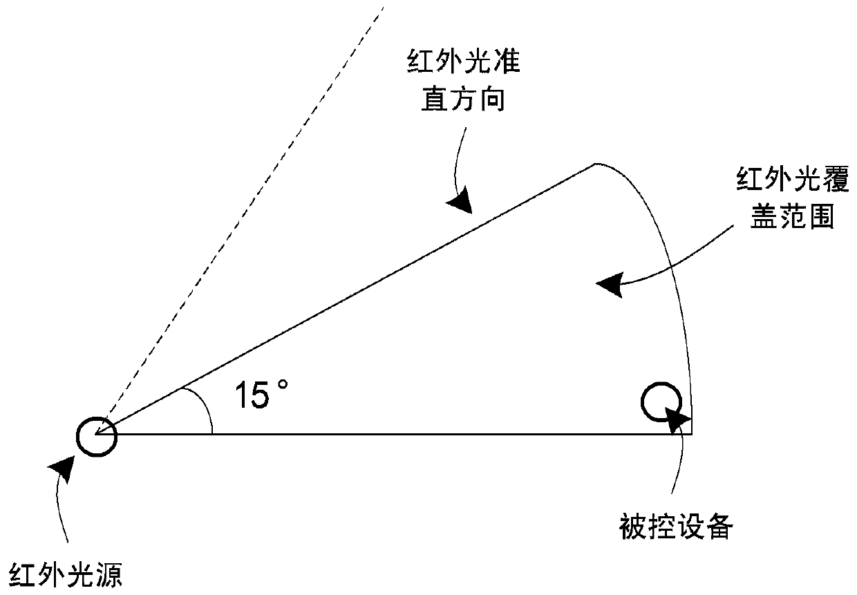
technical field [0001] The embodiments of the present invention belong to the technical field of remote control, and in particular relate to an infrared emission angle adjustment structure, an infrared emission module and a remote control device using the infrared emission angle adjustment structure. Background technique [0002] In some remote-controlled devices, such as TV sets and air conditioners, infrared remote control is a commonly used remote control method. Communication to realize the function of remote control. [0003] The infrared light source used in the existing infrared emission modules is generally an infrared LED, and the divergence half angle of the infrared LED currently on the market can only reach a minimum of 15°, such as figure 1 As shown, when remote control is carried out at a long distance, the infrared rays emitted by the infrared transmitter module can cover a large range. Often, when the infrared transmitter module (infrared LED) of the remote ...

Claims


Application Information

Patent Timeline
Patent Type & Authority Applications(China)
IPC IPC(8): G08C23/04H04B10/50H04B10/114
CPCG08C23/04H04B10/114H04B10/50
Inventor 刘芳
Owner SZ DJI TECH CO LTD
Learn More