Optical components and 3d measuring equipment

A technology for optical components and measuring equipment, which is applied in the field of 3D measurement and can solve the problems of inability to meet product application, size and high energy consumption.

Active Publication Date: 2020-10-27
NANJING HUAJIE IMI TECH CO LTD
View PDF4 Cites 0 Cited by
  • Summary
  • Abstract
  • Description
  • Claims
  • Application Information

AI Technical Summary

Problems solved by technology

However, traditional 3D measurement equipment cannot meet the requirements, especially the optical components used in the 3D measurement equipment, its size and energy consumption are relatively large, which cannot meet these demanding product applications

Method used


Image

  • Optical components and 3d measuring equipment
  • Optical components and 3d measuring equipment
  • Optical components and 3d measuring equipment

Examples


Embodiment Construction

[0041] Specific embodiments of the present invention will be described in detail below in conjunction with the accompanying drawings. It should be understood that the specific embodiments described here are only used to illustrate and explain the present invention, and are not intended to limit the present invention.

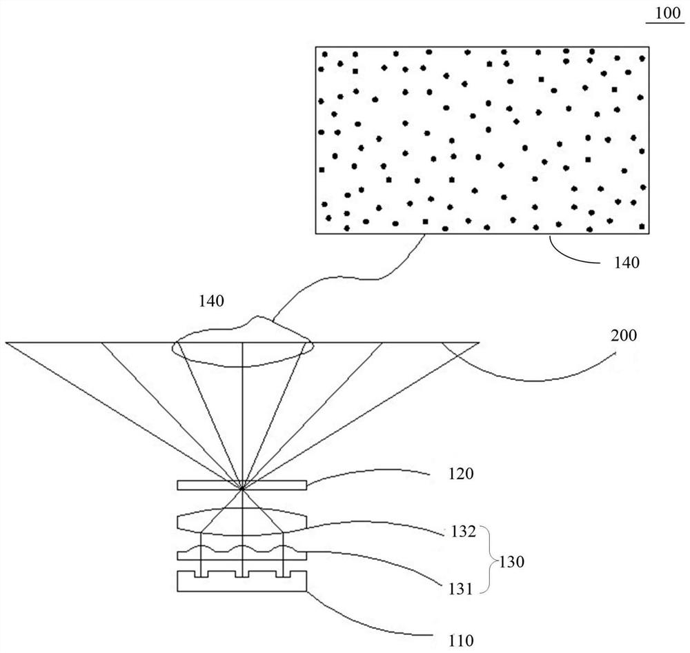
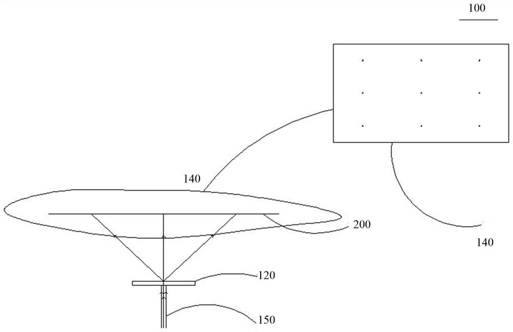
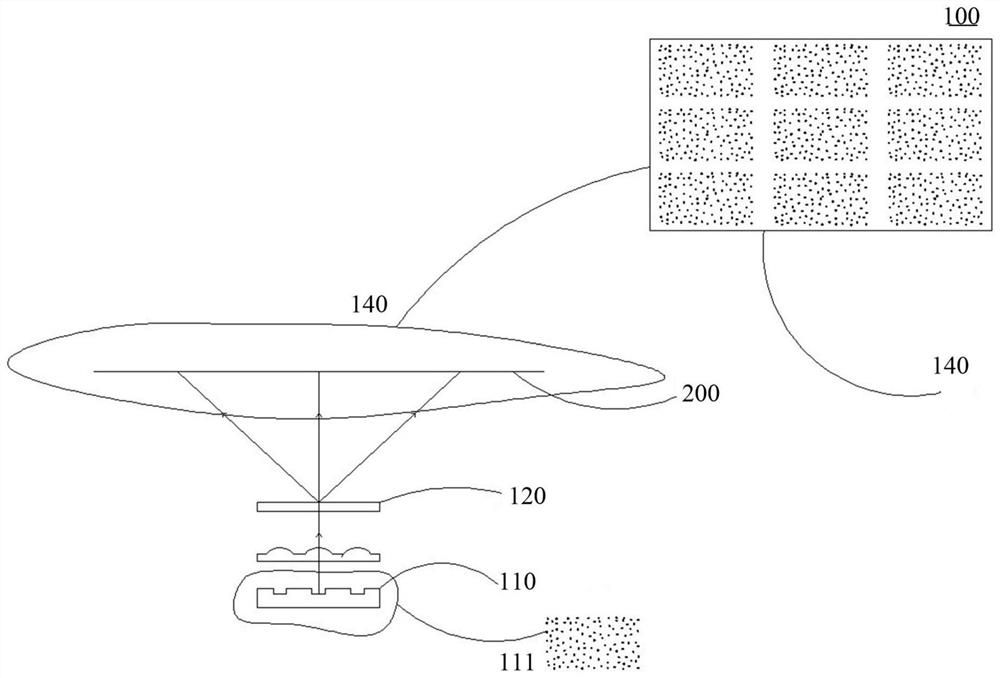
[0042] refer to figure 1 , figure 2 and image 3 , the first aspect of the present invention relates to an optical component 100 . The optical assembly 100 is suitable for a 3D measuring device (not shown in the figure). Wherein, the optical assembly 100 includes a light source unit 110 , an imaging unit 120 and an adjustment unit 130 located between the light source unit 110 and the imaging unit 120 .

[0043] The above-mentioned light source unit 110 includes a plurality of light sources 111, and the plurality of light sources 111 are arranged in multiple rows and columns, preferably, they may be arranged in an array. The light emitted by each light sour...


PUM


Abstract

The present invention discloses an optical module and a 3D measurement device. The optical module is suitable for the 3D measurement device. The optical module comprises a light source unit, an imaging unit and a regulation unit located between the light source unit and the imaging unit. The light source unit comprises a plurality of light sources which are in multi-line and multi-row arrangement mode, and the emergent rays of the light sources are perpendicular to the surface of the light extraction side of the light source unit; and the regulation unit comprises a plurality of regulation lenses, each regulation lens corresponds to one light source, the regulation lenses can receive and regulate the emergent rays emitted by the corresponding light sources to allow the emergent rays to be regulated as parallel rays, and the imaging unit is configured to receive and copy the parallel rays to form preset optical images. The optical module is compact in structure and reduced in thickness so as to reduce the thickness of the 3D measurement device applied to the optical module and allow the application range of the 3D measurement device to be much wider.

Description

technical field [0001] The invention relates to the technical field of 3D measurement, in particular to an optical component and a 3D measurement device including the optical component. Background technique [0002] In general, current 3D measurement equipment is more and more applied to computers, mobile phones, TVs, robots, medical equipment and other products for in-depth image capture, such as face recognition, gesture recognition, and spatial positioning. [0003] In order to meet these demanding product applications, the volume of 3D measurement equipment is required to be smaller and smaller, and the power consumption is also required to be strictly controlled. Due to the wide range of applications of the product, the product has high requirements for the temperature tolerance. However, the traditional 3D measurement equipment cannot meet the requirements, especially the optical components used in the 3D measurement equipment, its size and energy consumption are relat...

Claims


Application Information

Patent Timeline
Patent Type & Authority Patents(China)
IPC IPC(8): G01B11/24G02B27/09
CPCG01B11/24G02B27/0955
Inventor 周晓军王行盛赞李朔李骊杨高峰
Owner NANJING HUAJIE IMI TECH CO LTD
Why Eureka
Try Eureka