Annular external fixator assembly capable of correcting rotation deformity

An external fixator and rotational deformity technology, applied in the field of medical devices, can solve the problems of fracture malunion, complex structure, delayed bone union, etc., and achieve the effect of correcting rotational deformity

Pending Publication Date: 2020-03-24
SHANGHAI SIXTH PEOPLES HOSPITAL
View PDF0 Cites 0 Cited by
  • Summary
  • Abstract
  • Description
  • Claims
  • Application Information

AI Technical Summary

Problems solved by technology

[0002] In traditional external fixation, a splint or plaster is usually used to fix the fracture outside the skin. Since the splint or plaster is separated from the fracture by soft tissues such as muscles, blood vessels, and nerves, there is room for movement at the fracture end, so it is difficult to achieve anatomical alignment. The subsidence of swelling caused by trauma and the disuse of muscle atrophy caused by the inability of the affected limb to move effectively exacerbates the loosening of external fixation, which easily causes serious consequences of malunion, delayed union or nonunion of fractures
[0003] The traditional annular external fixator can fix, extend, and migrate bones well, and can easily correct angulation and malalignment deformities, but the traditional annular external fixator is very troublesome to correct rotational deformities, and the structure is relatively complicated

Method used


Image

  • Annular external fixator assembly capable of correcting rotation deformity
  • Annular external fixator assembly capable of correcting rotation deformity
  • Annular external fixator assembly capable of correcting rotation deformity

Examples


Embodiment Construction

[0023] The present invention will be further described below in conjunction with the accompanying drawings and specific embodiments, but not as a limitation of the present invention.

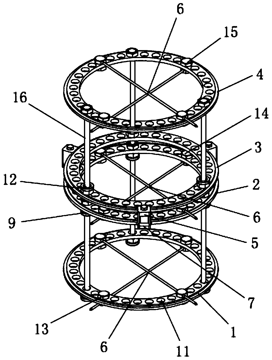
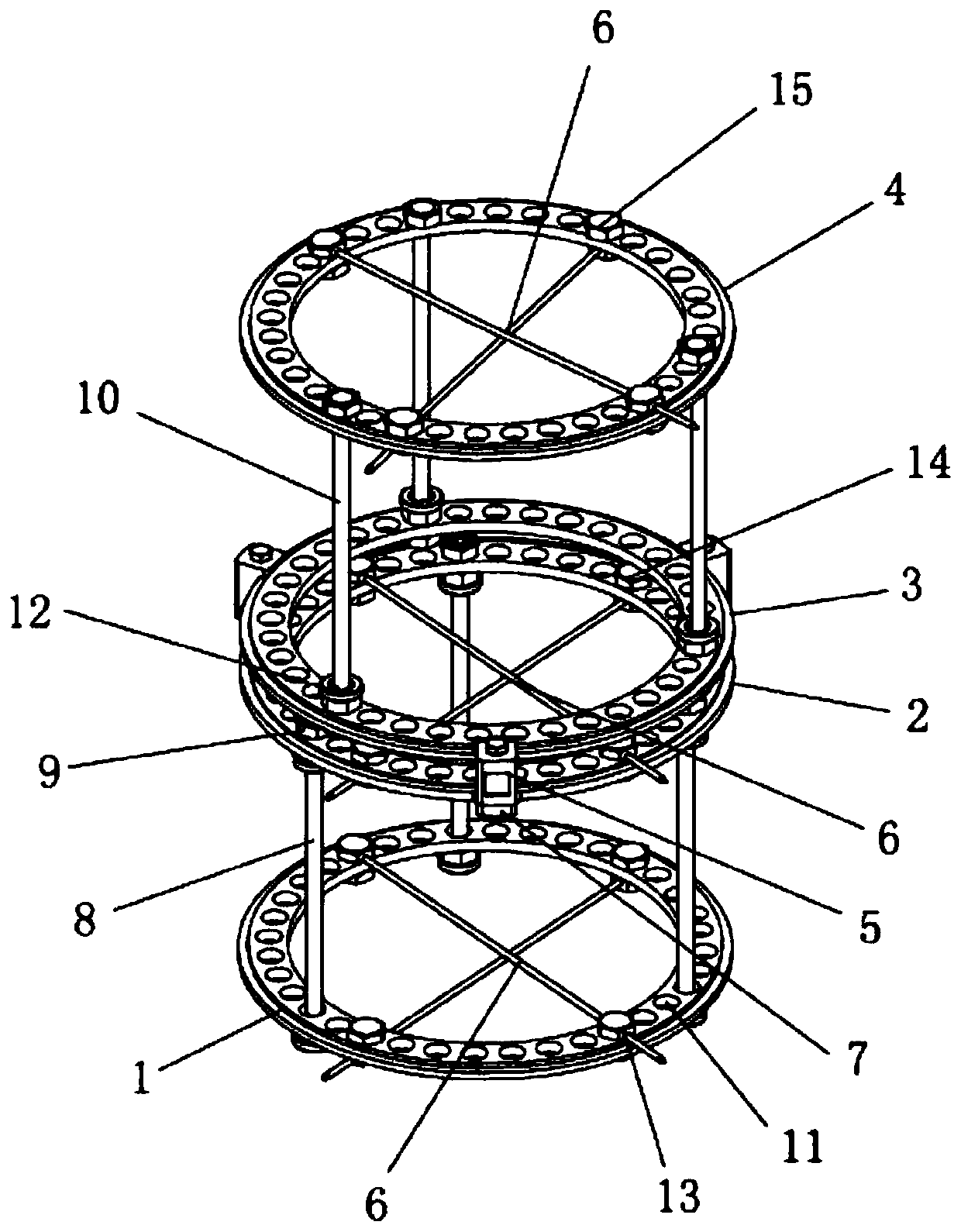
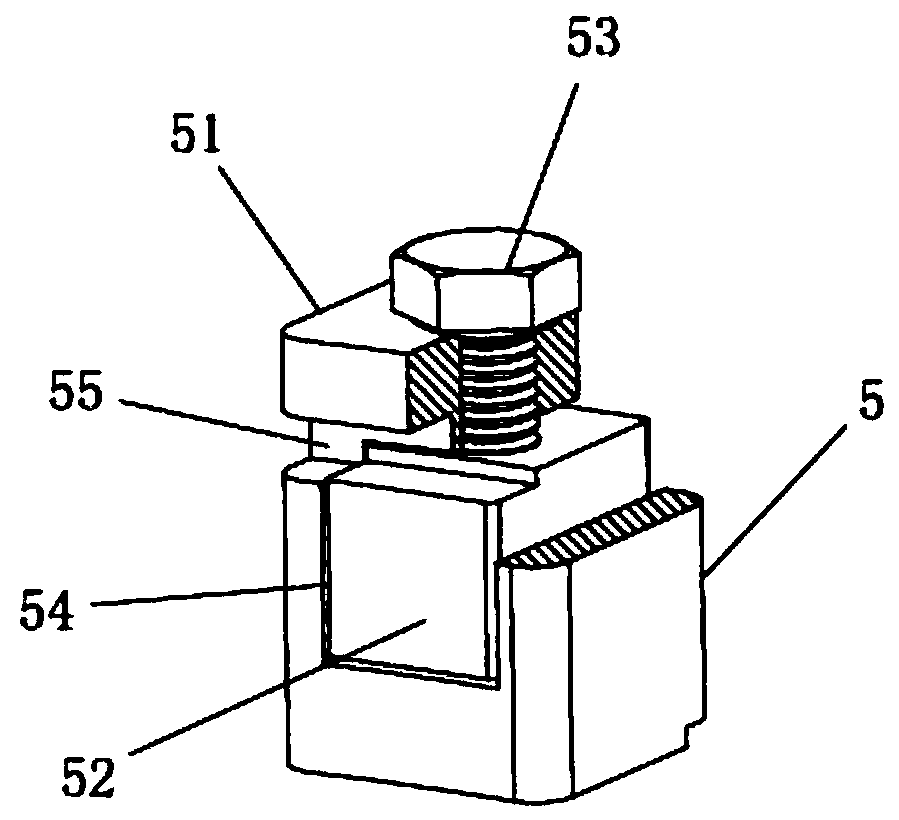
[0024] figure 1 It is a structural view of the annular external fixator assembly capable of correcting rotational deformity in the present invention, figure 2 It is a schematic diagram of the rotation state of the annular external fixator assembly capable of correcting the rotation deformity in the present invention, image 3 It is a structural schematic diagram of the rotating ring fixing assembly in the present invention, please refer to Figure 1 to Figure 3 As shown, a preferred embodiment is shown, and a circular external fixator assembly capable of correcting rotational deformity is shown, including: a first fixed ring 1, a second fixed ring 2, a rotating ring 3, a third Fixed ring 4, rotating ring fixed assembly 5 and Kirschner wire 6. The second fixed ring 2 is arranged on the upper ...


PUM


Abstract

The invention discloses an annular external fixator assembly capable of correcting rotation deformity. The invention relates to the technical field of medical instruments. The annular external fixatorassembly capable of correcting rotation deformity comprises a first fixing ring, a second fixing ring, a rotating ring, a third fixing ring, rotating ring fixing assemblies and kirschner wires; the second fixing ring is arranged on the upper side of the first fixing ring; the second fixing ring is opposite to the first fixing ring; the rotating ring is arranged on the upper side of the second fixing ring; the rotating ring is opposite to the second fixing ring; the third fixing ring is arranged on the upper side of the rotating ring; the third fixing ring is opposite to the rotating ring; a plurality of rotating ring fixing assemblies are uniformly arranged on the outer edge of the second fixing ring; wherein the first fixing ring is fixedly connected with the second fixing ring, the second fixing ring is rotatably connected with the rotating ring through the plurality of rotating ring fixing assemblies, the rotating ring is fixedly connected with the third fixing ring, and the firstfixing ring, the second fixing ring and the third fixing ring are respectively provided with two kirschner wires. The annular external fixator assembly has the characteristics of flexibility in use and convenience in adjustment.

Description

technical field [0001] The invention relates to the technical field of medical instruments, in particular to an annular external fixator assembly capable of correcting rotational deformities. Background technique [0002] In traditional external fixation, a splint or plaster is usually used to fix the fracture outside the skin. Since the splint or plaster is separated from the fracture by soft tissues such as muscles, blood vessels, and nerves, there is room for movement at the fracture end, so it is difficult to achieve anatomical alignment. The subsidence of swelling caused by trauma and the disuse of muscle atrophy caused by the inability of the affected limb to move effectively exacerbate the loosening of external fixation, thus easily causing serious consequences such as malunion, delayed union or nonunion of fractures. [0003] The traditional annular external fixator can fix, extend, and migrate bones well, and can easily correct angulation and malalignment deformitie...

Claims


Application Information

Patent Timeline
IPC IPC(8): A61B17/66
CPCA61B17/6425A61B17/66A61B2017/564
Inventor 盛加根张长青
Owner SHANGHAI SIXTH PEOPLES HOSPITAL
Why Eureka
Try Eureka