
Steel bar cutting machine

A steel bar cutting machine and steel bar technology, applied in the direction of clamps, manufacturing tools, etc., can solve the problems of steel bar slipping or skewing, the cutting surface of different steel bars is not neat enough, and the steel bar cutting machine lacks steel bar fixing devices, etc., so as to facilitate flow diversion and adjustment Effect

Active Publication Date: 2020-03-24
上海铭谷民防设备有限公司
View PDF7 Cites 1 Cited by
  • Summary
  • Abstract
  • Description
  • Claims
  • Application Information

AI Technical Summary

Problems solved by technology

[0004] The above-mentioned existing technical solutions have the following defects: the steel bar cutting machine lacks a fixing device for fixing the steel bars, which easily causes the steel bars to slip or skew during the cutting process, so that the cutting surfaces of different steel bars are not neat enough

Method used


Image

  • Steel bar cutting machine
  • Steel bar cutting machine
  • Steel bar cutting machine

Examples


Embodiment Construction

[0032] The present invention will be described in further detail below in conjunction with the accompanying drawings.

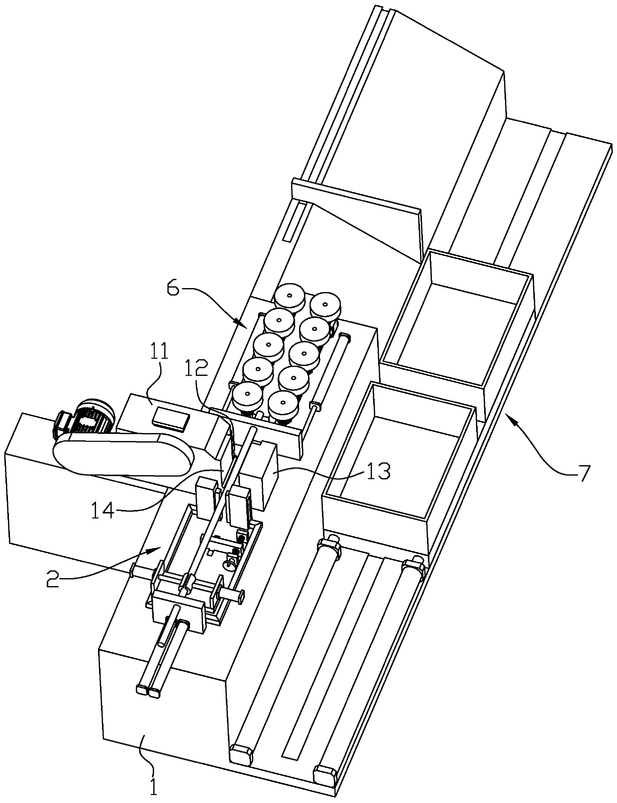
[0033] Such as figure 1 As shown, it is a steel bar cutting machine disclosed by the present invention, including a base 1, a mounting base 11 fixed to the base 1, a cutter 12 mounted on the mounting base 11, a fixing base 13 fixed to the base 1 and a The cutting groove 14 between the mounting seat 11 and the fixing seat 13, and the two sides of the base 1 are respectively equipped with a feeding structure 2 and a discharging structure.

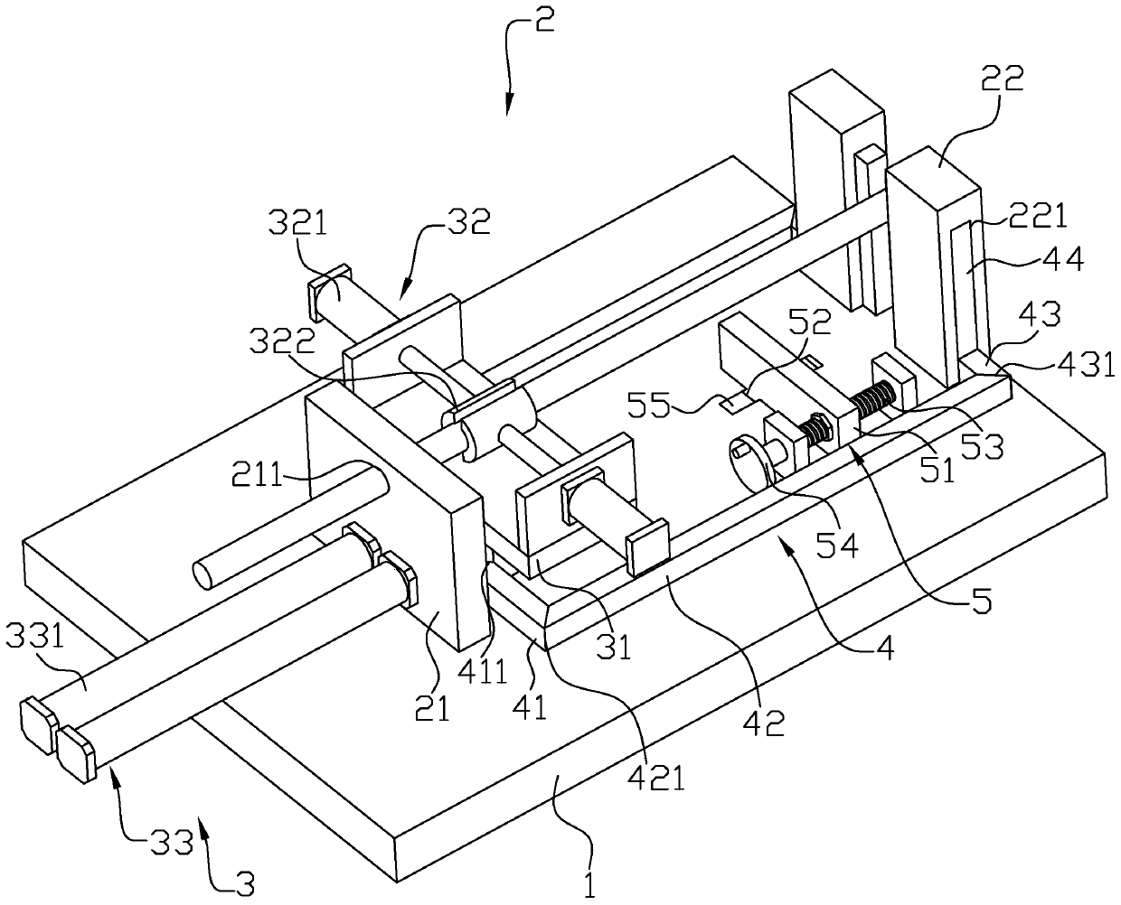
[0034] Such as figure 1 with figure 2 As shown, the feed structure 2 includes a first support plate 21, a transport device 3 and a second support plate 22 arranged in sequence along the transport direction of the steel bar; The transportation direction of steel bars is slidingly connected to the movable plate 31 of the base 1, the clamping mechanism 32 installed on the top of the movable plate 31 for fixing the steel bar...


PUM


Abstract

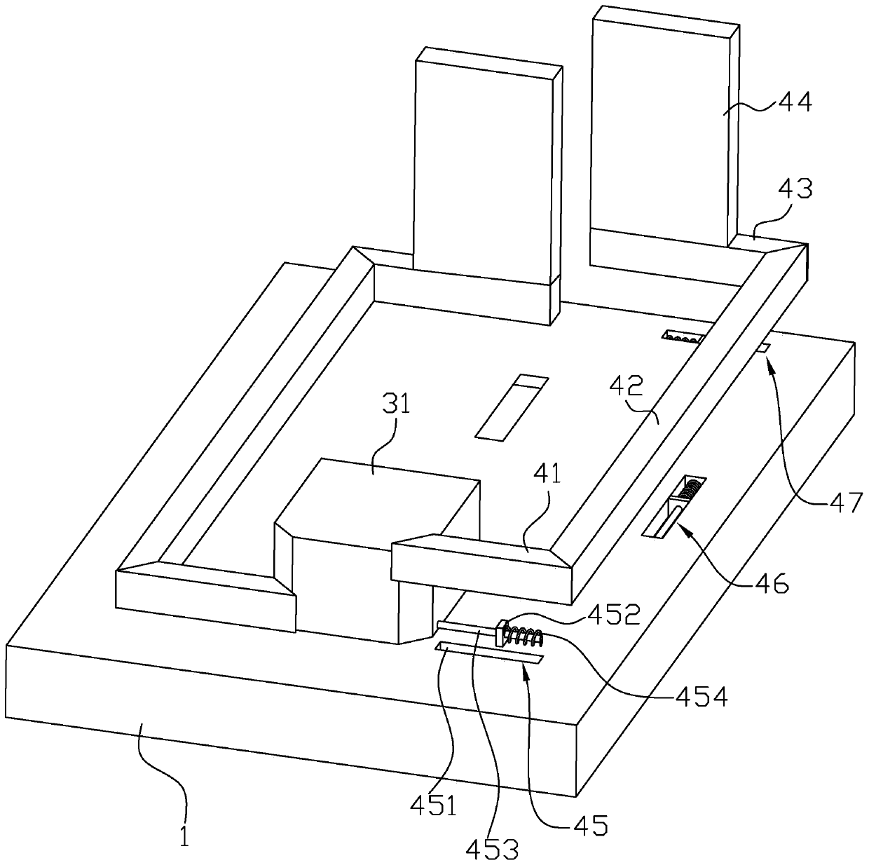
The invention relates to a steel bar cutting machine. The machine comprises a base, a mounting base, a cutter, a fixing base and a cutting groove, wherein the two sides of the base are provided with afeeding structure and a discharging structure correspondingly, the feeding structure comprises a first supporting plate, a conveying device and a second supporting plate, a limiting groove is formedin the top of the first supporting plate, the conveying device comprises a movable plate, a clamping mechanism and a driving mechanism, a fixing device is installed between the first supporting plateand the second supporting plate, the fixing device comprises two groups of fixing mechanisms, each group of fixing mechanisms comprises a first connecting block, a second connecting block, a third connecting block and a fixing plate, a strip-shaped hole is formed in one side of the second supporting plate, each of the opposite inner sides of the movable plate and each first connecting block is provided with a first inclined surface, each of the opposite inner sides of each first connecting block and the corresponding second connecting block is provided with a second inclined surface, each of the opposite inner sides of each second connecting block and the corresponding third connecting block is provided with a third inclined surface, and the base is provided with a first reset component, asecond reset component and a third reset component.

Description

technical field [0001] The invention relates to the technical field of steel bar processing, in particular to a steel bar cutting machine. Background technique [0002] At present, the steel bar cutting machine is a tool used for cutting steel bars. By placing the steel bar in the cutting groove reserved between the cutter mounting seat and the fixed seat, and controlling the sliding of the cutter set in the cutter mounting groove The pop-up cuts off the reinforcement. [0003] For the prior art, please refer to the Chinese utility model patent whose authorized announcement number is CN201669354U, which discloses a steel bar cutting machine and its housing. The housing includes a box part and a cutting part. The fixed knife seat and the movable knife seat, the fixed knife seat includes the basic part and the extension part which is integrally arranged along the feeding direction from the basic part, and there is a feeding material for feeding and putting in the steel bar be...

Claims


Application Information

Patent Timeline
Patent Type & Authority Applications(China)
IPC IPC(8): B21F11/00B21F23/00B25B5/06
CPCB21F11/00B21F23/00B25B5/061
Inventor 龚珙娣
Owner 上海铭谷民防设备有限公司
Learn More