Laminated glass adhesive film winding system and using method thereof

A technology of laminated glass and adhesive film, which is applied in the directions of winding strips, thin material handling, transportation and packaging, etc. It can solve the problems of lower production efficiency, insufficient locking, and the failure of the adhesive film reel to follow the rotation of the rotating roller, etc. , to achieve the effect of improving production efficiency and ensuring the effect of locking and positioning

Pending Publication Date: 2020-03-24
SHANDONG FANGDING SAFETY GLASS TECH CO LTD
0 Cites 2 Cited by

AI-Extracted Technical Summary

Problems solved by technology

[0003] Because the existing technology requires workers to do it manually, on the one hand, the locking device needs to be disassembled every time a roll of film is completed; on the other hand, the locking may no...

Abstract

The invention discloses a laminated glass adhesive film winding system, relates to the technical field of laminated glass adhesive film winding, and particularly belongs to a system device capable offixing an adhesive film winding drum and achieving winding and a using method of the system device. The system is characterized in that a main supporting mechanism comprises a rail assembly installedon the ground, a left rack and a right rack are fixed to a left end and a right end of the rail respectively, sliding table assemblies are respectively arranged above the left rack and the right rack,a power mechanism comprises a servo gear motor installed on a sliding block in the sliding table assembly, a main straight gear and a main bevel gear are assembled on an output shaft of the servo gear motor, a locking mechanism comprises power chucks, the power chucks are fixed to the left rack and the right rack through bearing pedestals respectively, an outer shaft is arranged outside an innershaft, extending outwards, of each power chuck in a sleeving mode, and an auxiliary straight gear, an auxiliary bevel gear and an auxiliary straight gear are assembled at outer extending ends of the inner shaft and the outer shaft respectively. The system is advantaged in that the locking and positioning effect of the adhesive film winding drum is guaranteed, and the positive effect of improving production efficiency of laminated glass adhesive film winding operation is achieved.

Application Domain

Webs handling

Technology Topic

ServoAdhesive +5

Image

  • Laminated glass adhesive film winding system and using method thereof
  • Laminated glass adhesive film winding system and using method thereof
  • Laminated glass adhesive film winding system and using method thereof

Examples

  • Experimental program(1)

Example Embodiment

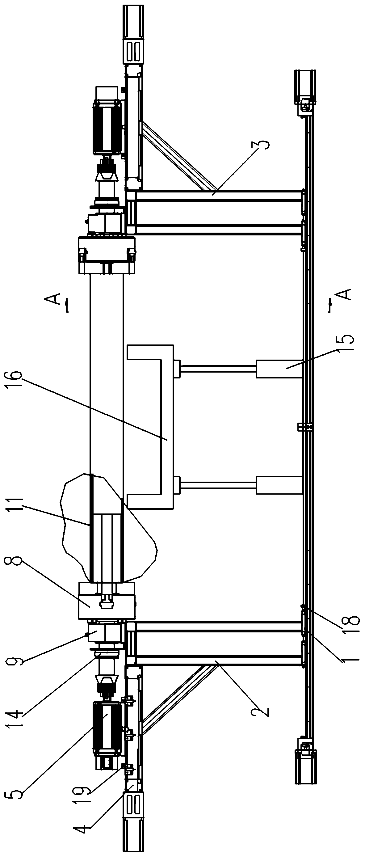
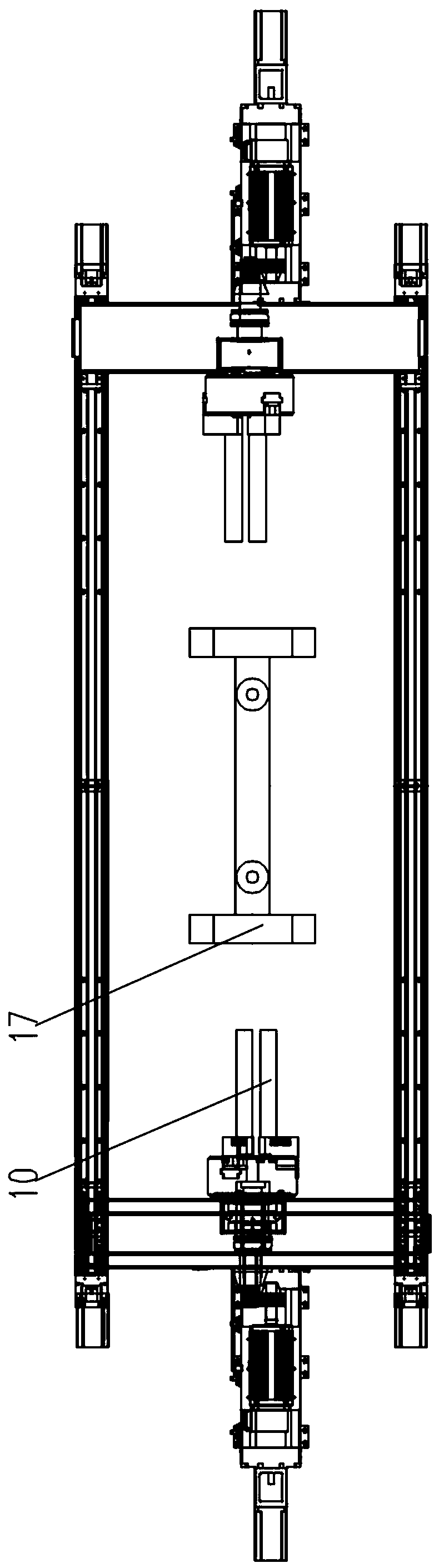
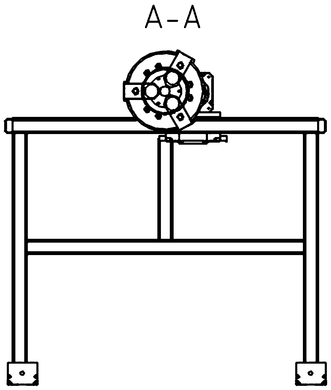
[0027] Such as Figure 1-5 As shown, the laminated glass glue film winding system provided by the present invention includes a main supporting mechanism, an auxiliary supporting mechanism, a power mechanism and a locking mechanism.
[0028] The main support mechanism includes a track assembly 1 installed on the ground. The track assembly is a KK60 standard linear module and includes a stepper motor. The left rack 2 and the right rack 3 are respectively fixed on the rail at the left and right ends of the rail. A sliding table assembly 4 is installed above the left and right racks. The sliding table assembly is MSY110 aluminum-based linear module Including motor.
[0029] The power mechanism includes a servo reduction motor 5 installed on the slider in the sliding table assembly. The output shaft of the servo reduction motor is equipped with a main spur gear 6-1 and a main bevel gear 7-1. Specifically, the main spur gear and the main bevel gear The gear is fixed on the output shaft of the servo motor with a flat key.
[0030] The locking mechanism includes a power chuck 8. The power chuck is a V series three-jaw real power chuck assembly. The power chuck is fixed on the left frame and the right frame respectively through the bearing seat 9. The jaws of the power chuck 10 extends to the inside of the film roll 11 at both ends of the film roll 11 and is matched with it. An outer shaft 13 is sheathed on the inner shaft 12 that extends outward from the power chuck. The outer extension ends of the inner shaft and the outer shaft are respectively equipped with a secondary spur gear 6-2 and a secondary bevel gear 7-2. Specifically, the secondary The spur gear and the auxiliary bevel gear are respectively fixed on the inner shaft and the outer shaft by flat keys, and the auxiliary spur gear and the auxiliary bevel gear mesh with the main spur gear and the main bevel gear respectively. In addition, an electromagnetic powder brake 14 is fitted on the outer shaft, and the electromagnetic powder brake is fixed on the left and right frames by bolts.
[0031] The auxiliary support mechanism includes a cylinder 15 and a support frame body 16 connected to the extension end of the cylinder. When the cylinder in the auxiliary support mechanism extends to the maximum range, the center axis of the film roll in the support frame body and the center of the power chuck The axis remains consistent. A U-shaped groove 17 is provided at the top of the support frame, and the U-shaped groove is supported on the bottom end of the film roll.
[0032] The system also includes a control box. The control box is equipped with a controller. The sliding table and the track are respectively provided with a forward limit proximity switch 18, a backward limit switch 19, a forward limit switch, a backward limit switch and a servo deceleration motor. , The sliding table motor of the sliding table assembly, the track motor of the track assembly, the electromagnetic powder brake, and the air cylinder are all connected to the control box and connected to the controller.
[0033] The method of using the laminated glass film winding system provided by the present invention mainly includes the following steps:
[0034] a. Preparation for the installation of the film winding system: the film roll is placed in the U-shaped groove of the support frame of the auxiliary support mechanism. After the air cylinder lifts the film roll in the support frame in place, the rail assembly drives the left frame, At the same time, the right frame moves to the center until the forward limit switch on the trigger track stops, and the jaws of the power chuck extend into the film roll. At this time, the electromagnetic powder brake is energized to lock the outer shaft so that it cannot rotate.
[0035] b. Locking and positioning of the film roll: The servo decelerating motor drives the inner shaft of the power chuck to rotate, and drives the claws of the power chuck to open outward and top the film roll and fix it, according to the set time In the range of 5-10s, the servo decelerating motor stops rotating to complete the positioning of the film roll.
[0036] c. Film roll rewinding film: The end of the film is fixed on the film roll, the sliding table motor starts and drives the servo reduction motor to move to the center, the auxiliary bevel gear and the motor output shaft assembled on the outer shaft of the power chuck The assembled main bevel gear meshes, the electromagnetic powder brake is powered off and the outer shaft is released. After the servo reduction motor moves into place, the cylinder drives the support frame to fall, and the servo reduction motor starts and drives the power chuck and the film roll on it to rotate , The film is then reeled on the film roll until the rewinding of a roll of film is completed, the servo decelerating motor stops. At this time, the electromagnetic powder brake is energized and the outer shaft is locked.
[0037] d. The film rewinding system is reset: After the rewinding of a roll of film is completed, the film is cut from the feeding end of the film, the slide motor is reversed, and the servo decelerating motor is driven to return to the initial position, that is, the slide is triggered After the reverse limit switch, the sliding table motor stops. At this time, the servo decelerating motor starts and reverses, driving the jaws of the power chuck from the chuck state to the loose state inside the film roll, and the cylinder starts and drives The support frame body is lifted up to drag the film roll after the rewinding, the track motor starts and reverses, and drives the left frame and the right frame to return to the initial position, that is, after triggering the backward limit switch on the track, the track motor stop.
[0038] f. Repeat the above process a-d to realize the film winding operation of multiple film rolls.

PUM

no PUM

Description & Claims & Application Information

We can also present the details of the Description, Claims and Application information to help users get a comprehensive understanding of the technical details of the patent, such as background art, summary of invention, brief description of drawings, description of embodiments, and other original content. On the other hand, users can also determine the specific scope of protection of the technology through the list of claims; as well as understand the changes in the life cycle of the technology with the presentation of the patent timeline. Login to view more.

Similar technology patents

Precise extrusion molding method of thin wall long-pipe shaped parts bland and special mould

InactiveCN101332476AIncreased dimensional accuracy and material utilizationIncrease productivity
Owner:HENAN UNIV OF SCI & TECH

Spot welding machine

ActiveCN102114572AIncrease productivityGuarantee spot welding quality
Owner:NINGBO MINTH AUTOMOTIVE PARTS RES&DEV CO LTD

UV-curable colored paint composition

Owner:JIANGSU KUANGSHUN PHOTOSENSITIVITY NEW MATERIAL

Classification and recommendation of technical efficacy words

Why Eureka
Try Eureka