Steel wire pay-off device

A technology of pay-off device and steel wire, which is applied in the directions of transportation and packaging, transportation of filamentous materials, and processing of thin materials, etc., can solve the problems of single-wire arching of stranded conductors, reducing production efficiency, and uneven tension. The effect of popularization and easy operation, improving production efficiency and uniform pay-off tension

Pending Publication Date: 2020-03-24
白银有色长通电线电缆有限责任公司 +1
View PDF0 Cites 1 Cited by
  • Summary
  • Abstract
  • Description
  • Claims
  • Application Information

AI Technical Summary

Problems solved by technology

In the production process of aluminum steel-reinforced wire, when the steel wire is continuously paid off, the existing steel wire pay-off device cannot make the inner ring of the large plate steel traveler and the installation tube on the lower pallet tense to form a whole, so that When the steel wire pays off, it is easy to produce uneven tension, which leads to the random winding or breaking of the steel wire, which affects the smooth progress of the steel wire pay-off; and causes the frequent shutdown and start-up of the steel wire pay-off device, which cannot guarantee the uniform speed of the steel-reinforced aluminum strand production equipment. Running, the stranding pitch of the stranding conductor is different, prone to quality problems such as single-wire arching and looseness of the stranding conductor, reducing production efficiency and affecting the quality of the finished product of the steel-reinforced aluminum strand

Method used


Image

  • Steel wire pay-off device
  • Steel wire pay-off device
  • Steel wire pay-off device

Examples


Embodiment Construction

[0019] The present invention will be described in detail below in conjunction with the accompanying drawings.

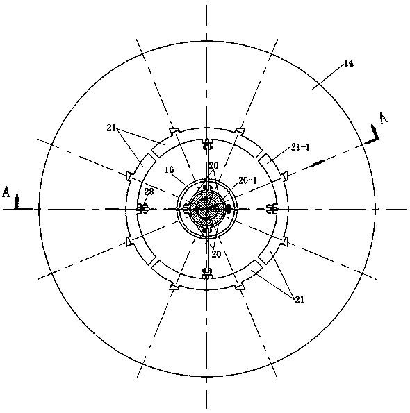
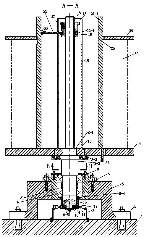
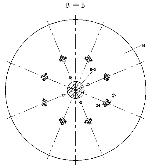
[0020] Such as Figure 1-4 As shown, a wire pay-off device provided by the present invention includes a fixed seat 5 and two brackets 2 installed inside the fixed seat 5, a bearing seat 6 is installed in the fixed seat 5, and two sets of upper and lower sets are installed in the bearing seat 6. Tapered roller bearings 7, a second spacer sleeve 31 is installed between the two sets of tapered roller bearings 7. Bearing seat gland 9 is installed above the tapered roller bearing 7 on the bearing seat 6; a main shaft 8 is pierced inside the tapered roller bearing 7, and the main shaft 8 is divided into primary shafts 8 sharing the same center line from top to bottom -1, the secondary shaft 8-2, the tertiary shaft 8-3, the fourth shaft 8-4 and the fifth shaft 8-5, the bottom of the fifth shaft 8-5 is equipped with a tension disc 11 through the tension disc gland 10, A DB...


PUM


Abstract

The invention discloses a steel wire pay-off device and belongs to the field of cable auxiliary production equipment. On the basis of an existing steel wire pay-off device, a separation sleeve, a pushrod and other components are additionally adopted; an installation cylinder is set to be an adjustable installation cylinder composed of four single adjustable installation cylinders evenly distributed along the center line of a main shaft. When a fastening nut is rotated, the separation sleeve can be pushed to enable the vertical position of the push rod to be changed, so that the adjustable installation cylinder is made to undergo axial displacement; and the inner ring of a steel wire ring is tensioned, so that the steel wire ring and the steel wire paying-off device form an integrated body. The steel wire pay-off device is uniform in steel wire pay-off tension. With the steel wire pay-off device adopted, the phenomenon that steel wires are wound disorderly or broken by pulling is completely eradicated; smooth pay-off operation can be guaranteed without the frequent stopping and starting of the pay-off device required; and the production efficiency of steel wire aluminum stranded wires is improved.

Description

technical field [0001] The invention relates to the field of cable auxiliary production equipment, in particular to a steel wire pay-off device. Background technique [0002] The current transfer process has a "skin effect", that is, it flows along the surface of the wire. Since the quality of aluminum is smaller than that of iron and copper, its conductivity is better than that of iron, but the strength of aluminum is not good, and it is soft and easy to break. Using a steel core can increase the strength of the wire without affecting the conductivity. Therefore, high-voltage transmission lines are usually used Steel core aluminum stranded wire. In the production process of aluminum steel-reinforced wire, when the steel wire is continuously paid off, the existing steel wire pay-off device cannot make the inner ring of the large plate steel traveler and the installation tube on the lower pallet tense to form a whole, so that Uneven tension tends to occur when the steel wir...

Claims


Application Information

Patent Timeline
IPC IPC(8): B65H49/32B65H59/06
CPCB65H49/32B65H59/06B65H2701/36
Inventor 焦伟
Owner 白银有色长通电线电缆有限责任公司
Why Eureka
Try Eureka