Method for estimating the reversely calculated control points of NURBS

A technology of control point and tool position point, which is applied in the field of spline tool position trajectory fitting of numerical control technology, can solve the problems of low calculation efficiency and many calculation times, and achieve the effect of reducing calculation.

Active Publication Date: 2020-03-24
XIANGTAN UNIV
View PDF8 Cites 4 Cited by
  • Summary
  • Abstract
  • Description
  • Claims
  • Application Information

AI Technical Summary

Problems solved by technology

[0007] For this reason, the embodiment of the present invention provides a method for NURBS reverse control point estimation to solve the problems of many calculation times and low calculation efficiency in the prior art

Method used


Image

  • Method for estimating the reversely calculated control points of NURBS
  • Method for estimating the reversely calculated control points of NURBS
  • Method for estimating the reversely calculated control points of NURBS

Examples


Embodiment

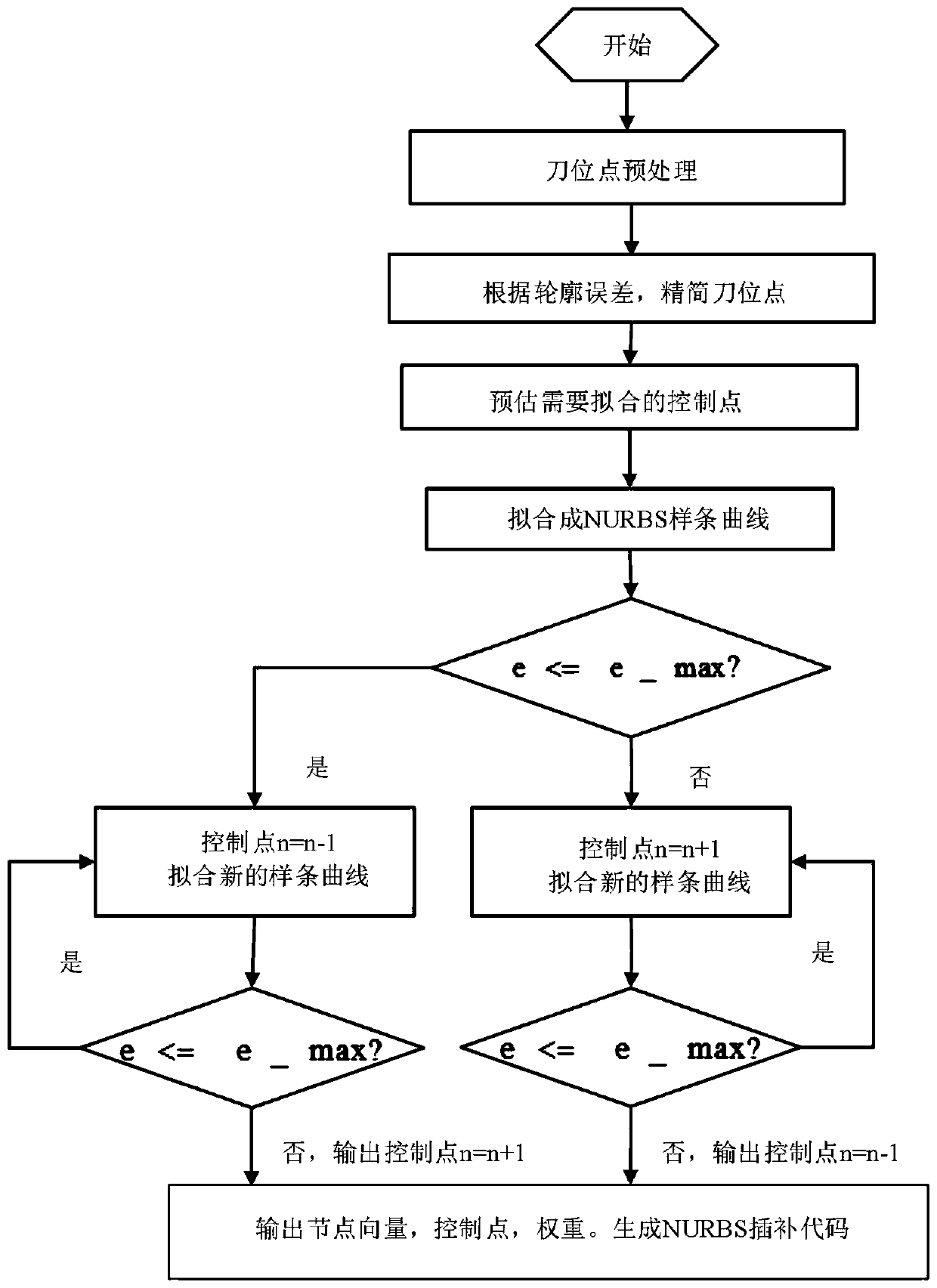
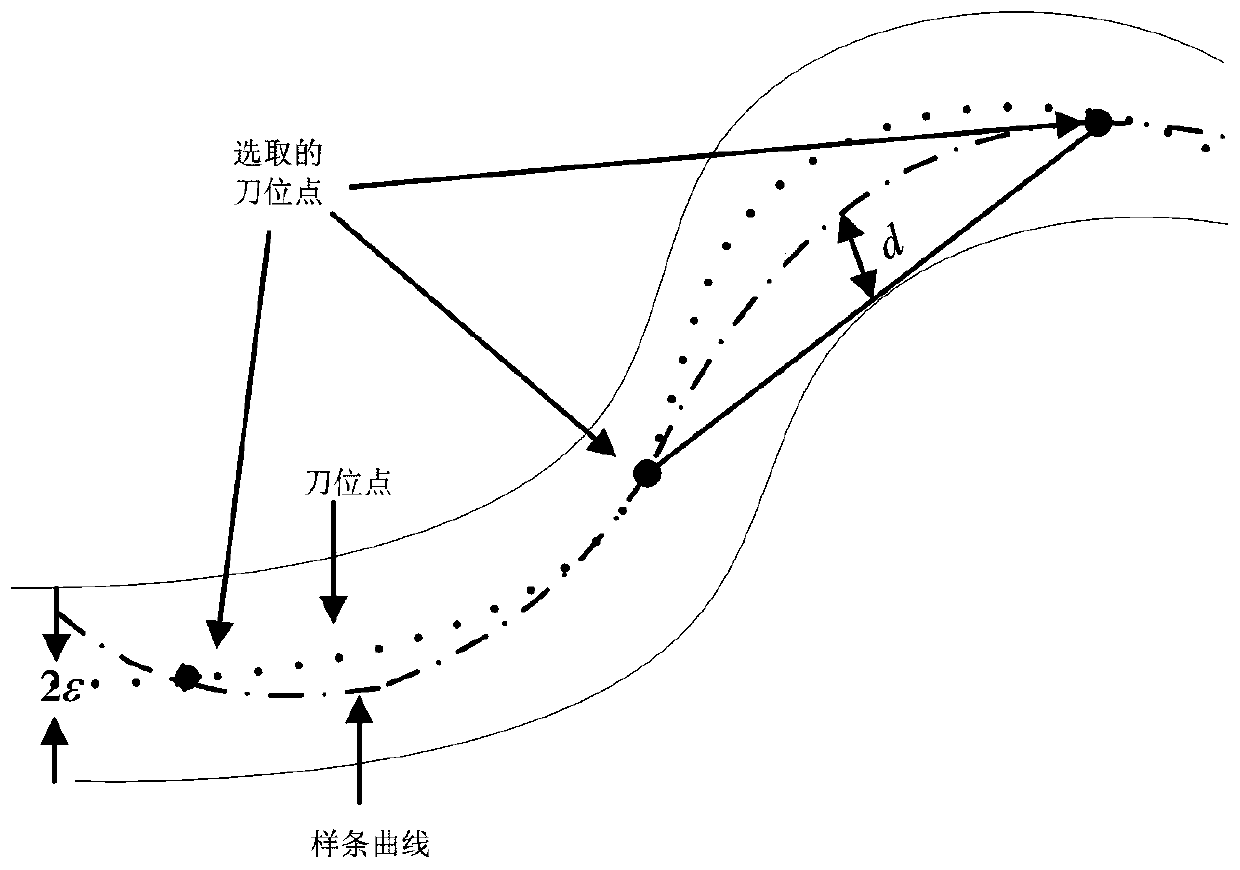
[0042] Step 1: According to the known tool location points and the contour error of the NURBS curve, the tool location points are simplified, and the tool location points representing the typical contour are selected;

[0043] Such as figure 2 As shown, enter the tool location point P 0 ,..., P n , Give contour error d r As a control factor. Let P k Point is the starting point, P j As the end point, where 0≤k≤j-2 and k+2≤j≤n. Pick the middle point P i , Ki To the straight line P k P j The error d. Compare d with threshold d r , If d is greater than d r , Continue to search down, otherwise save P j Point to P k =P j As a new starting point, P j =P j+2 As the new end point, continue searching.

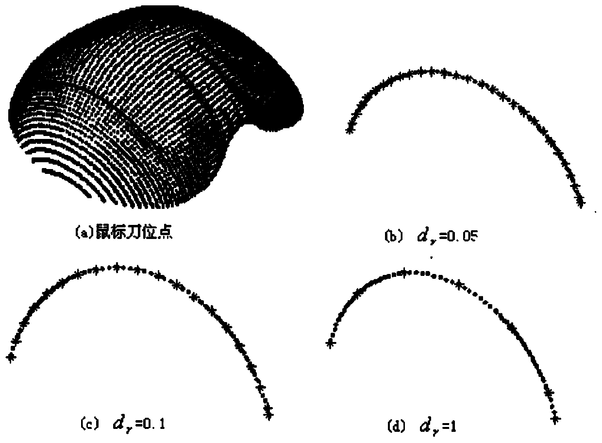
[0044] Such as image 3 As shown, a mouse tool position point is taken as an example, and different contour errors are used as thresholds to obtain different simplified tool position points.

[0045] Step 2: Take the simplified back tool position point as the initial value, usually the simpl...


PUM


Abstract

The embodiment of the invention discloses a method for estimating the reversely calculated control points of an NURBS. The method is characterized by comprising the following steps of 100, simplifyingthe cutter location points through the known cutter location points and a set error threshold, and selecting the cutter location points representing a typical contour; 200, taking the simplified cutter location points as the control initial values, and calculating the control points required for interpolating the cutter location points; 300, fitting the NURBS by taking the calculated control points as the fitting initial values, and calculating a contour error after fitting; 400, comparing the contour error after each time of calculation with the error threshold value, increasing or decreasing the control points according to a comparison result, and repeating the steps 200 to 400 until the minimum control points meet the error threshold value. According to the method, the defects of a traditional mode are overcome, the more accurate control points are estimated according to the known contour threshold value, and on the basis, the needed control points are calculated through multiple iterations, so that the reversely calculation efficiency of the NURBS can be greatly improved.

Description

Technical field [0001] The embodiment of the present invention relates to the technical field of spline tool position trajectory fitting of numerical control technology, and specifically relates to a method for predicting control points in reverse NURBS. Background technique [0002] The CNC machine tool is an efficient automatic processing equipment, which automatically processes the processed parts in strict accordance with the processing procedures. Usually the machine tool has the function of small line and arc interpolation. With the continuous development of CNC technology, the interpolation function of the CNC system is increasing. The more abundant, the NURBS spline interpolation function is an important manifestation of high-end CNC machine tools. [0003] NURBS curve is widely used in CAD modeling of parts, but it is necessary to offset the modeling curve and other reasons. Generally, NURBS curve is not directly used as the tool location path of CNC machining. A more reas...

Claims


Application Information

Patent Timeline
Patent Type & Authority Applications(China)
IPC IPC(8): G05B19/4099G05B19/4103
CPCG05B19/4099G05B19/4103G05B2219/33003G05B2219/34135
Inventor 吴继春阳广兴方海国尹硕辉周会成
Owner XIANGTAN UNIV
Why Eureka
Try Eureka