Current transformer air guide sleeve and GIS equipment

A technology of current transformers and shrouds, which is applied in the direction of inductors, circuits, transformers, etc., can solve problems such as water ingress and easy gaps, achieve vertical dimensional accuracy and be easy to control, and prevent rainwater from entering the current transformer for diversion Effects inside the hood

Inactive Publication Date: 2020-03-24
HENAN PINGZHI HIGH VOLTAGE SWITCHGEAR +2
View PDF5 Cites 0 Cited by
  • Summary
  • Abstract
  • Description
  • Claims
  • Application Information

AI Technical Summary

Problems solved by technology

[0004] The purpose of the present invention is to provide a current transformer shroud, which is used to solve the problem that the existing current transformer shroud is prone to gaps when it is connected to the outer peripheral surface of the lower end flange of the disconnector, resulting in water ingress inside. At the same time, the presen

Method used


Image

  • Current transformer air guide sleeve and GIS equipment
  • Current transformer air guide sleeve and GIS equipment

Examples


Embodiment Construction

[0029] Embodiments of the present invention will be further described below in conjunction with the accompanying drawings.

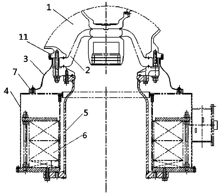
[0030] Embodiment 1 of the GIS equipment described in the present invention includes a disconnector 1, a current transformer feedthrough busbar housing 5 connected with the disconnector 1 by bolts, and a device for isolating the current transformer feedthrough busbar housing 5 and the disconnector 1 The insulating basin 2, the current transformer 6, the current transformer cover 4 covering the current transformer 6, and the current transformer shroud 3 connecting the current transformer cover 4 and the isolating switch 1.

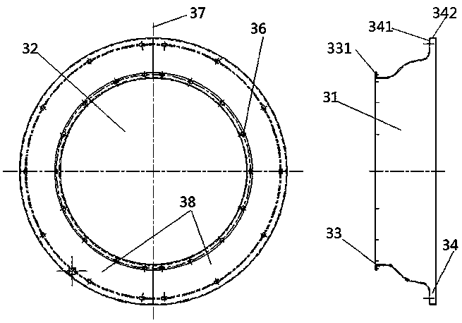
[0031] The current transformer shroud 3 includes a cylindrical cover body 31, and the cylindrical cover body 31 is equally divided into two identical arc-shaped plates 38 by a section 37 passing through its axis, and the two arc-shaped plates 38 are assembled into a The installation of the cylindrical cover body 31 can facilitate the ...


PUM


Abstract

The invention relates to a current transformer air guide sleeve and GIS equipment. The GIS equipment comprises a current transformer outer cover, an isolating switch and a current transformer flow guide cover, the current transformer flow guide cover comprises a cylindrical sleeve body, the cylindrical cover body wraps the connecting part of the insulating basin and the current transformer straight-through bus shell; the upper end of the cylindrical cover body is connected with a lower-end flange of the isolating switch; wherein the lower end of the cylindrical cover body is connected with a current transformer outer cover, the upper end of the cylindrical cover body comprises an annular connecting piece which is fixed with the upper edge of the cylindrical cover body and extends outwardsalong the radial direction of the cylindrical cover body, and the annular connecting piece is provided with a connecting hole which is correspondingly connected with an axial connecting hole arrangedon a flange at the lower end of the isolating switch. By using the GIS equipment provided by the invention, the problem that water enters the current transformer air guide sleeve due to the fact thata gap is easy to occur when the current transformer air guide sleeve is connected with the outer peripheral surface of the lower end flange of the isolating switch can be effectively solved.

Description

technical field [0001] The invention relates to a current transformer shroud and GIS equipment. Background technique [0002] When GIS equipment is in use, if the isolating switch is in a current loop, an induced current will be generated. Usually, an insulating basin is used to separate the isolating switch from the current transformer feed-through bus casing, so as to ensure that the current transformer feed-through bus casing There will be no induced current flowing on the ground, which avoids the influence of the induced current on the measurement accuracy of the current transformer; at the same time, the current transformer shroud is used to connect the isolation switch and the current transformer cover, so that a current path is formed between the two, and the induction The current is directed to the current transformer housing, which in turn leads to ground. [0003] A Chinese patent document with the announcement number CN203659614U published on June 18, 2014 descri...

Claims


Application Information

Patent Timeline
IPC IPC(8): H01F27/34H01F38/30H02B13/035
CPCH01F27/34H01F38/30H02B13/035
Inventor 柳少枫季新明张克选赵利军刘彦军段阿利舒金磊刘锋李建征陈瑞旭李耀文杨永欢路继伟李晓培史春玲曾春艳
Owner HENAN PINGZHI HIGH VOLTAGE SWITCHGEAR
Why Eureka
Try Eureka