Gas-insulated switchgear

a switchgear and gas-insulated technology, applied in switchgear arrangements, non-enclosed substations, substations, etc., can solve the problems of complex structure, difficult manufacture, and long planning period for tank manufactur

Inactive Publication Date: 2005-10-06
MITSUBISHI ELECTRIC CORP
View PDF7 Cites 36 Cited by
  • Summary
  • Abstract
  • Description
  • Claims
  • Application Information

AI Technical Summary

Benefits of technology

[0009]FIG. 2 is a sectional side view showing the basic configuration of the module of the present invention.
[0022] According to the gas-insulated switchgear of the present invention, by removing unnecessary equipments from the basic module and by connecting the modules in which the removed equipments are connected by short-circuiting conductors and the modules in which the opening portions are closed are connected with a gas section spacer, a necessary circuit configuration can be obtained, so that it can be easily adapted to any circuit configuration, making the circuit planning easy and realizing the standardization of the module.
INDUSTRIAL APPLICABILITY
[0023] As has been apparent from the foregoing description, according to the present invention, the gas-insulated switchgear in which main circuit components are accommodated within a tank hermetically filled with an electrically insulating gas comprises at least one switchgear module in which a disconnector with a grounding switch and an electrically insulating frame capable of supporting an interrupter including a vacuum valve are disposed in the tank in a vertically stacked relationship, and in which said disconnector and said vacuum valve are connected between their movable rods. Therefore, a gas-insulated switchgear can be obtained in which the module tanks are the same to each other in dimensions and configuration, and that can be adapted to various electric equipments to be accommodated within the module.

Problems solved by technology

In the conventional switchgear, the first and the second modules are different in tank size from each other, so that panel configurations at the tank rear side must be hook-shaped, making the structure complex and the manufacture difficult.
Also, since the tanks of the first and the second modules are different according to the equipments to be accommodated, the outer diameter dimension and structure of the tanks had to be changed according to the equipments to be housed, requiring a long period of time for planning of the tank manufacture.

Method used


Image

  • Gas-insulated switchgear
  • Gas-insulated switchgear
  • Gas-insulated switchgear

Examples


embodiment 1

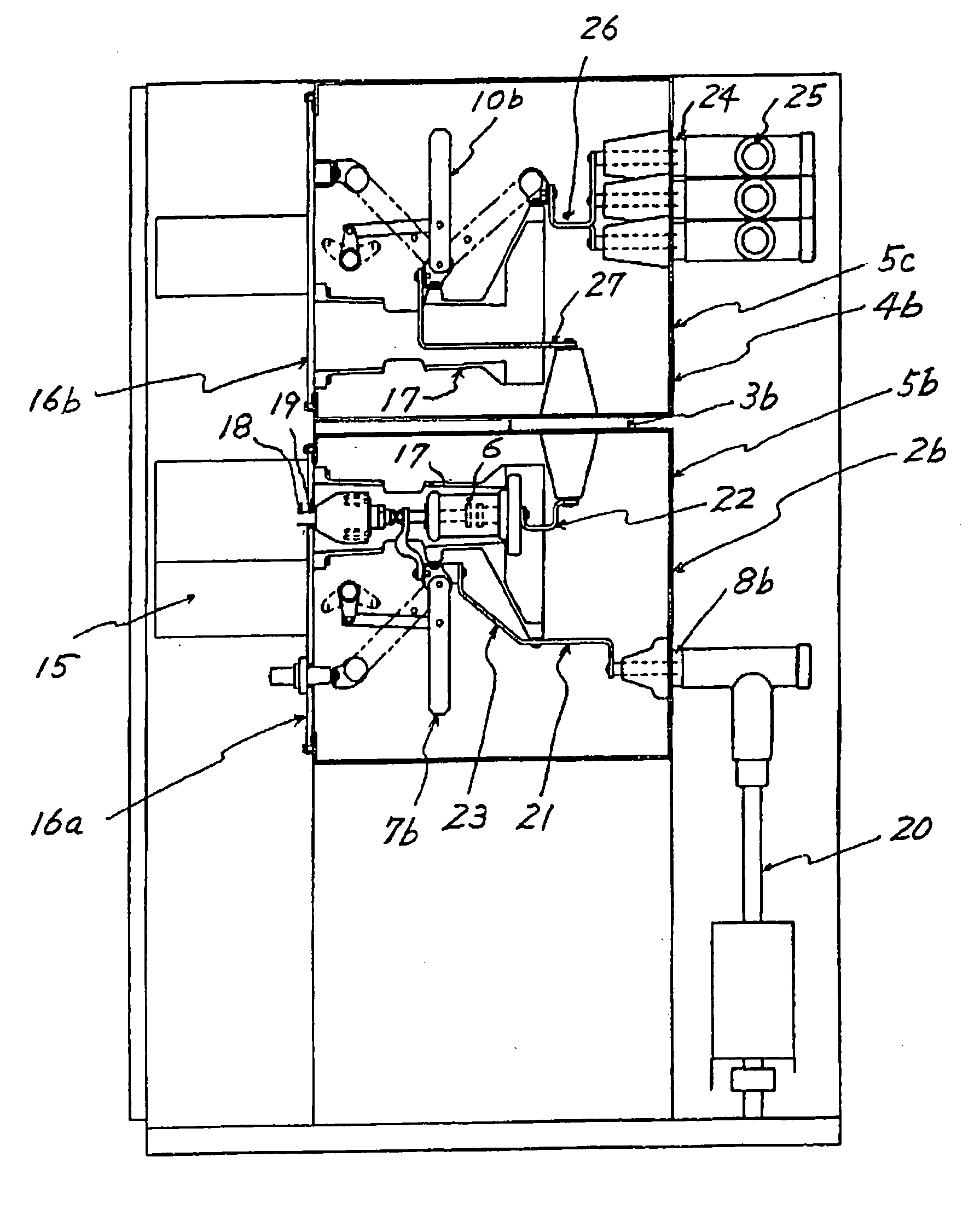
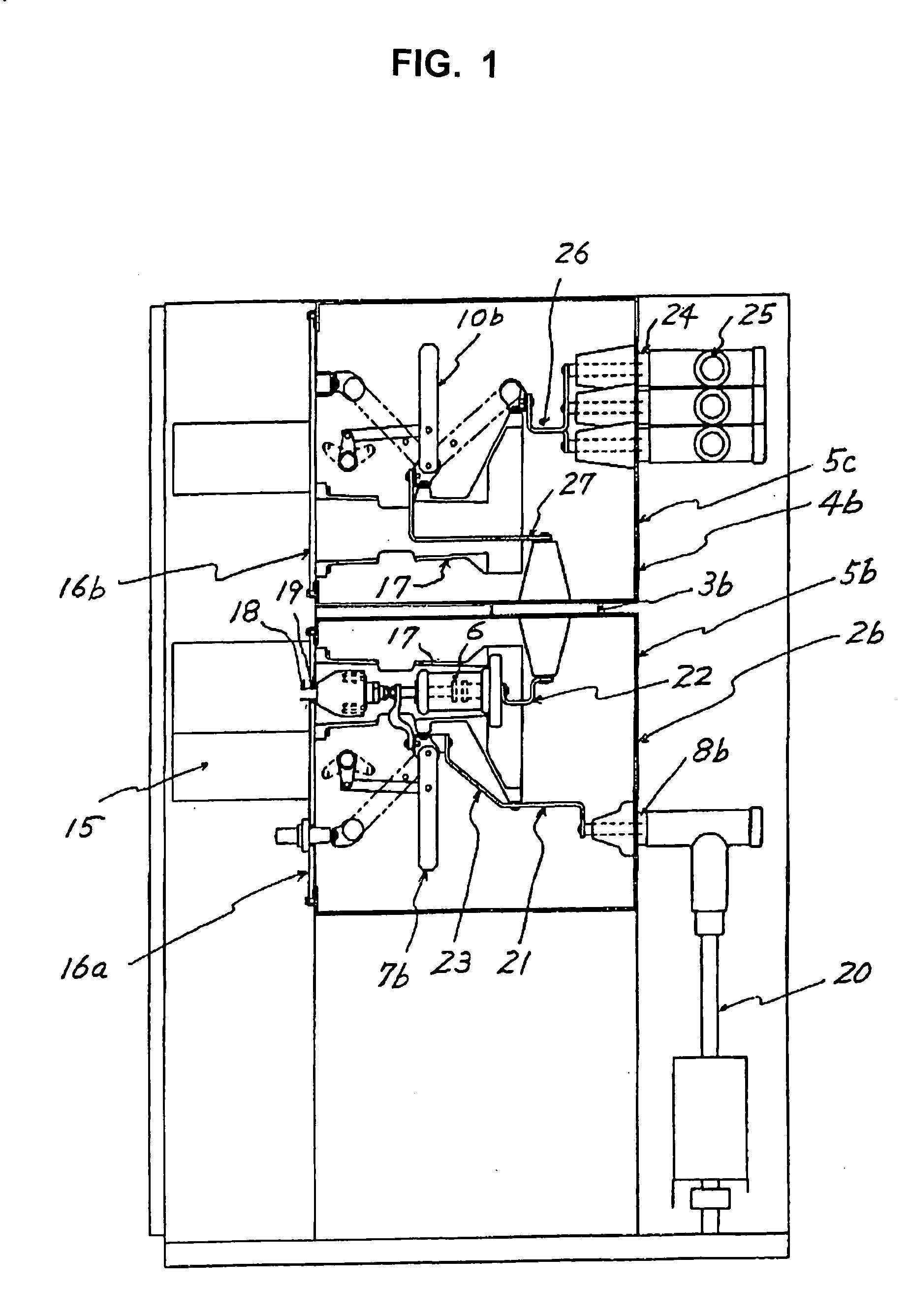
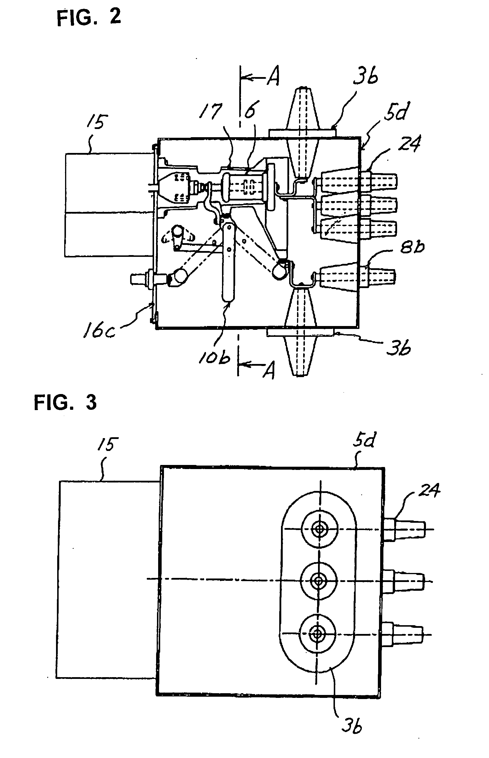
[0016] As illustrated in FIG. 1, the gas-insulated switchgear comprises a first module 2b and a second module 4b, the respective tanks 5b and 5c thereof having identical outer diameter dimension and configuration. In the illustrated example, each of the tanks 5b and 5c are of a substantially square configuration having substantially equal depth, width and height dimensions, but may equally be of a rectangular prallelopiped configuration.

[0017] The first module tank 5b has at its front face an opening portion to which a mounting plate 16a is hermetically attached. Attached to the rear face of the mounting plate 16a are an electrically insulating cylinders 17 in which interrupters 6 are accommodated and grounding switches 7b, and operating rods 18 for driving the interrupters 6 and the grounding switches 7b extending through a hole formed in the mounting plate 16a are connected to operating units 15 attached to the front face of the mounting plate 16a. Packings 19 maintains the herme...

embodiment 2

[0020] As shown in FIG. 7, similarly to the first embodiment, the first module 2b and the second module 4b (the equipments within the tank is changed to a disconnector with a grounding switch instead of a grounding switch) are provided and a third module 28 is mounted under the first module 2b via the gas section spacer 3b. The third module tank 28 similar to other tanks has at the front face of the tank an opening portion, to which a mounting plate 16d is hermetically attached. At the rear face of the mounting plate 16d, insulating cylinders 17 and grounding switches 7b disposed under the insulating cylinders 17 are mounted. The gas section spacers 3b are electrically connected to lightning arresters 29 and the grounding switches 7b by connecting conductors 30.

embodiment 3

[0021] As illustrated in FIG. 8, two gas-insulated switchgear modules are used and the positions of the bus bars 25 of a fourth module 31 are at the same height as those of the first embodiment illustrated in FIG. 1 and can be connected to them. Each of the fourth module 31 and a fifth module 32 is provided above or below the insulating cylinder 17 with a disconnector 10b with a grounding switch, and the power cable bushings 8b and the bus bars 25 for connecting to the respective individual circuits are attached to the rear face of the tank. Also, there is no gas section spacer is interposed between the fourth module 31 and the fifth module 32 and the mounting hole for the gas section spacer is closed.

[0022] According to the gas-insulated switchgear of the present invention, by removing unnecessary equipments from the basic module and by connecting the modules in which the removed equipments are connected by short-circuiting conductors and the modules in which the opening portions ...


PUM


Abstract

For simple structure and easy manufacture, module tanks have a common standardized size so that the same tank is applicable even when the components to be accommodated are changed. The basic structure of the module is arranged so that all of the interrupter, the disconnector with the grounding switch, the bus bar bushing, the cable connecting bushing and the gas section spacer can be mounted, and necessary main circuit components depending upon the circuit to be used are left behind and unnecessary main circuit components are short-circuited by a short-circuiting conductor, and that the tank opening portions are either left un-worked during manufacture or closed by a cover. The bus bar bushings and the cable connecting bushings are attached at the rear face of the tank and the gas section spacer is disposed on the top or bottom face of the tank. A lightning arrester in lieu of interrupter may be accommodated within an insulating cylinder housing the main circuit of the interrupter.

Description

TECHNICAL FIELD [0001] This invention relates to a gas-insulated switchgear. BACKGROUND ART [0002] A conventional gas-insulated switchgear, as described in Japanese Patent Laid-Open No. 2001-311614, for example, has a first module mounted on a mount bed and a second module mounted on the first module via a gas section spacer. Within a tank of the first module, interrupters and grounding switches are accommodated and bushings for connecting cables are attached to the bottom face of the tank. A tank of the second module is smaller than the tank of the first module and has disconnectors with grounding switches accommodated therein and bus bar bushings to which bus bars are connected are attached on upper portion of the second module tank. Also, the first module and the second module are connected via a gas section spacer that can maintain hermetic seal of the respective tanks. On the tank front side of each of the first module and the second module, an opening portion is disposed, to w...

Claims


Application Information

Patent Timeline
Patent Type & Authority Applications(United States)
IPC IPC(8): H02B13/02H01H33/66H02B13/035
CPCH01H31/003H02B13/035H01H33/6661H02B13/045
Inventor ARIOKA, MASAHIRO
Owner MITSUBISHI ELECTRIC CORP
Why Eureka
Try Eureka