Switch disconnector for galvanic direct current interruption

A technology of direct current and direct current power supply, applied in the direction of high voltage/high current switch, electric switch, circuit, etc., can solve the problems of inability to guarantee electrical separation, scrapping, and inability to guarantee personnel protection.

Active Publication Date: 2012-02-08
ELLENBERGER POENSGEN
View PDF8 Cites 34 Cited by
  • Summary
  • Abstract
  • Description
  • Claims
  • Application Information

AI Technical Summary

Problems solved by technology

However, the disadvantage is that such mechanical switching contacts are destroyed very quickly due to the arc formed when the contacts are opened, or additional expenditure is required to enclose and cool the arc, which is usually achieved by corresponding mechanical switch to achieve
[0005] If,

Method used


Image

  • Switch disconnector for galvanic direct current interruption
  • Switch disconnector for galvanic direct current interruption
  • Switch disconnector for galvanic direct current interruption

Examples


Embodiment Construction

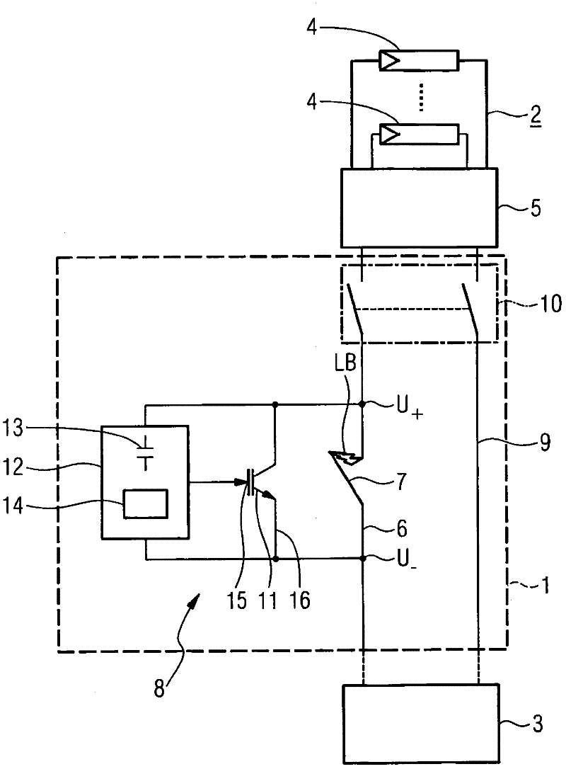
[0029] figure 1 The circuit breaking device 1 is schematically shown. In this embodiment, the circuit breaking device is connected between the photovoltaic generator 2 and the inverter 3. The photovoltaic generator 2 includes a number of solar modules 4, which are guided parallel to each other to a common generator junction box 5, which is approximately used as an energy collection point.

[0030] In the main current path 6 representing the positive electrode, the circuit-breaking device 1 comprises a switch contact 7 also referred to below as a mechanical switch and a semiconductor electronic device 8 connected in parallel therewith. The mechanical switch 7 and the semiconductor electronic device 8 form a self-sufficient hybrid disconnect switch. In the circuit breaker device 1 (and therefore the entire facility), the return line 9 representing the negative electrode can be connected to another hybrid circuit breaker 7, 8 in a manner and method not described in detail.

[0031] N...


PUM


Abstract

The invention relates to a disconnecting apparatus (1) for direct current interruption between a direct current source (2) and an electrical device (3), in particular between a photovoltaic generator and an inverter, with a current-conducting mechanical switching contact (7a, 7b) and with semiconductor electronics (8) connected in parallel with the switching contact (7a, 7b). The semiconductor electronics (8) are non-conducting when the switching contact (7a, 7b) is closed, wherein a control input (15) of the semiconductor electronics (8) is wired with the switching contact (7a, 7b) in such a way that, when the switching contact (7a, 7b) opens, an arc voltage (ULB)generated as a result of an arc (LB) via the switching contact (7a, 7b) switches the semiconductor electronics (8) to be conducting.

Description

Technical field [0001] The present invention relates to a circuit breaking device for cutting off direct current between a direct current power supply and an electrical device, the circuit breaking device having a mechanical switch contact for guiding current and a semiconductor electronic device connected in parallel with the switch contact. Here, "DC power supply" is especially understood as a photovoltaic generator (solar facility), and "electrical device" is especially understood as an inverter. Background technique [0002] Known from DE 20 2008 010 312 U1 is a photovoltaic installation or a solar installation with so-called photovoltaic generators, which in that respect consist of solar modules that are grouped into sub-generators. These solar modules In that respect, it is connected in series or in a parallel branch (Strang). The sub-generator outputs its DC power through two terminals, and the DC power of the entire photovoltaic generator is fed into the AC grid through ...

Claims


Application Information

Patent Timeline
IPC IPC(8): H01H9/54H01H33/59
CPCH01H9/542H01H2009/544H01H2009/546H01H33/59H01H9/54
Inventor 米夏埃尔·瑙曼托马斯·齐策尔斯贝格尔弗兰克·格迪南
Owner ELLENBERGER POENSGEN
Why Eureka
Try Eureka