Automatic traction device for lower-limb fracture setting operation

A traction device and automatic technology, applied in the direction of the fixator, etc., can solve the problems affecting the accuracy of traction reset, the inability to adjust the difference between the Kirschner wire calf support plate or thigh support plate, and device inclination, so as to improve the quality of surgery and improve the operation quality. efficiency effect

Pending Publication Date: 2020-03-27
THE THIRD HOSPITAL OF HEBEI MEDICAL UNIV +2
View PDF1 Cites 11 Cited by
  • Summary
  • Abstract
  • Description
  • Claims
  • Application Information

AI Technical Summary

Problems solved by technology

[0006] 1. The stability of the device is low. In the case of keeping the angle of the bent legs unchanged, the overall height of the device is adjusted by the four jacking bolts at the bottom. It is difficult to adjust the four jacking bolts synchronously, and it is easy to cause the whole device to tilt ;
[0007] 2. The device as a whole is supported by only four jacking bolts and is prevented from being placed on the operating bed. Due to the certain deformability of the surface of the operating bed, the device is placed unstable. During the operation, there is shaking or the jacking bolts sink, causing the device to tilt , affect the accuracy of traction reduction, and then affect the smooth progress of the operation;
[0008] 3. The traction bow at

Method used


Image

  • Automatic traction device for lower-limb fracture setting operation
  • Automatic traction device for lower-limb fracture setting operation
  • Automatic traction device for lower-limb fracture setting operation

Examples


Embodiment Construction

[0060] The technical solutions in the embodiments of the present invention are clearly and completely described below in conjunction with the accompanying drawings in the embodiments of the present invention. Obviously, the described embodiments are part of the embodiments of the present invention, not all of them. Based on the embodiments of the present invention, all other embodiments obtained by those skilled in the art without making creative efforts belong to the protection scope of the present invention.

[0061] In the following description, a lot of specific details are set forth in order to fully understand the present invention, but the present invention can also be implemented in other ways different from those described here, and those skilled in the art can do it without departing from the meaning of the present invention. By analogy, the present invention is therefore not limited to the specific examples disclosed below.

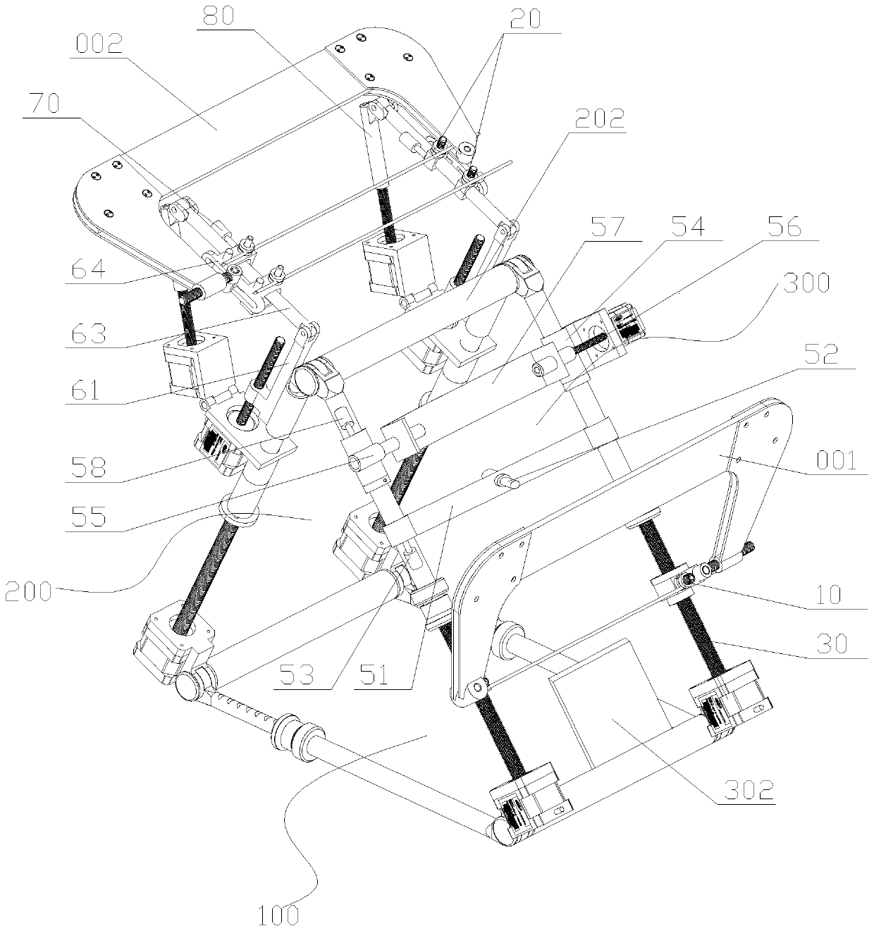
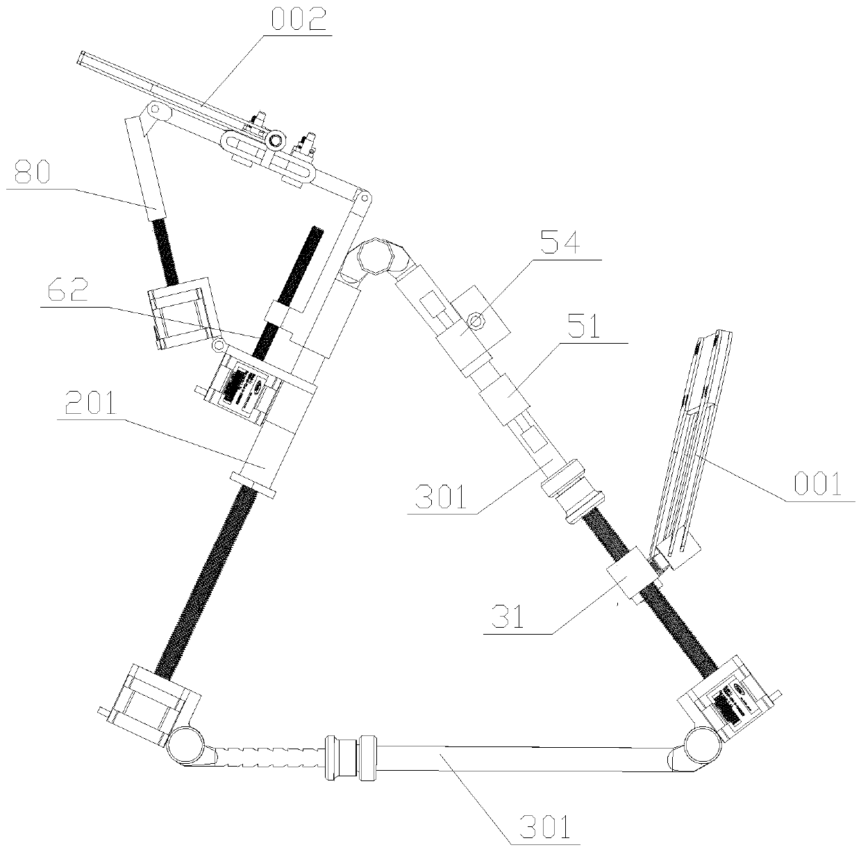
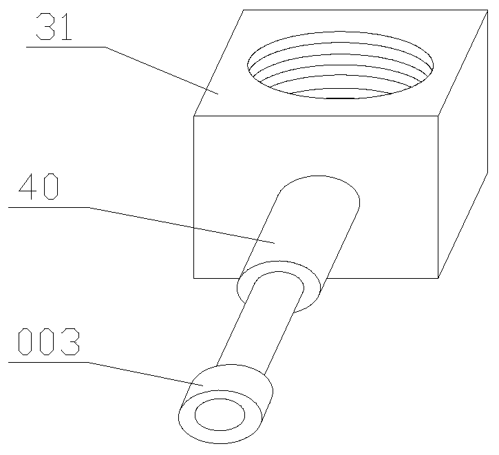
[0062] Such as Figure 1 ~ Figure 3 As ...


PUM


Abstract

The invention discloses an automatic traction device for a lower-limb fracture setting operation. According to the invention, a supporting frame is of a triangular structure, is used for supporting alower limb of a patient to form and keep a leg bending state, and comprises a horizontally-arranged supporting bottom surface, and a thigh bearing surface and a shank bearing face which are oppositelyarranged two ends of the supporting bottom surface, wherein the end parts of every two adjacent surfaces are hinged; and the lengths of all the surfaces can be adjusted and locked through edge adjusting mechanisms. A tibia kirschner wire mounting position is provided with two tibia kirschner wire mounting structures which are respectively arranged at two sides of the shank supporting surface. Twothighbone kirschner wire mounting positions are arranged in parallel at an interval, and each thighbone kirschner wire mounting position is provided with two thighbone kirschner wire mounting structures which are respectively arranged at two sides of the thigh supporting surface.

Description

technical field [0001] The invention relates to the technical field of orthopedic medical devices, in particular to an automatic traction device for lower limb fracture osteosynthesis, which is suitable for femoral and tibial intramedullary nail implantation and percutaneous bone plate implantation osteosynthesis. Background technique [0002] Femoral and tibial fractures are common clinical fractures. Due to the strong muscle strength of the legs, patients with tibial fractures often appear shortened and deformed under the pull of the muscles. It is difficult to reset, restore its length and maintain it effectively during the operation. If the anatomical reduction cannot be performed during the operation, complications such as malunion and poor alignment of the lower limbs may occur after the operation, which may lead to traumatic arthritis or osteoarthritis, seriously affecting the limb function and quality of life of the patient. [0003] Intramedullary nailing or percuta...

Claims


Application Information

Patent Timeline
IPC IPC(8): A61B17/88A61B17/92
CPCA61B17/8866A61B17/8869A61B17/921
Inventor 陈伟张英泽侯志勇朱燕宾连晓东金霖马利杰赵亚攀张建辉
Owner THE THIRD HOSPITAL OF HEBEI MEDICAL UNIV
Why Eureka
Try Eureka