Train wing plate decelerating device based on worm wheel and worm transmission

A deceleration device and worm drive technology, which is applied in transportation and packaging, pneumatic brakes, railway car body parts, etc., can solve the problems of large driving force for opening the flap, harsh installation position selection, and occupation of the inner space of the car body, so as to ensure Safe and reliable, easy processing and installation, convenient installation and maintenance

Active Publication Date: 2017-10-03
TONGJI UNIV
View PDF3 Cites 2 Cited by
  • Summary
  • Abstract
  • Description
  • Claims
  • Application Information

AI Technical Summary

Problems solved by technology

Wind resistance braking Most of the wind resistance braking devices that have been disclosed so far realize the opening and closing control through hydraulic pressure, air pressure or gear structure, but there are problems such as the large driving force required to open the flap, the selection of the installation location is relatively harsh, and the interior space of the car body is occupied, etc. question

Method used


Image

  • Train wing plate decelerating device based on worm wheel and worm transmission
  • Train wing plate decelerating device based on worm wheel and worm transmission
  • Train wing plate decelerating device based on worm wheel and worm transmission

Examples


Embodiment Construction

[0026] The present invention will be further described below with reference to the embodiments shown in the accompanying drawings.

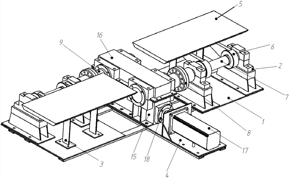
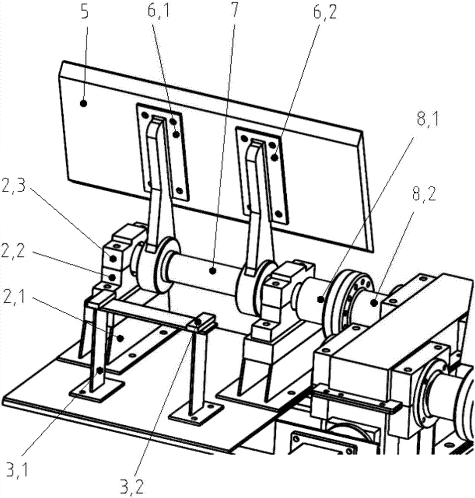
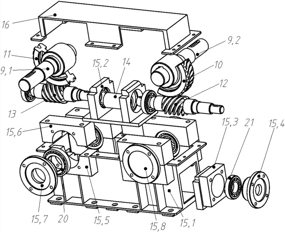
[0027] like figure 1 and figure 2 As shown, the present invention first provides a worm gear-driven train wing plate reduction device, which includes four main parts: a positioning mechanism, a wing plate mechanism, a worm gear mechanism and a drive mechanism.

[0028] Specifically, it mainly includes a mounting base 1, a wing plate bearing seat and a bracket 2 (that is, the above-mentioned rotating shaft support), an electromagnet and a bracket 3, a motor mounting frame 4, a wing plate surface 5, a wing plate arm 6, a wing plate Rotating shaft 7, wing plate-worm gear coupling 8 (that is, the above-mentioned wing plate rotating shaft coupling), worm wheel shaft 9, left-handed worm wheel ring 10, right-handed worm wheel ring 11, left-handed worm shaft 12, right-handed worm shaft 13, worm - Worm coupling 14 , lower case 15 , upper case 16 , step...


PUM


Abstract

The invention provides a train wing plate decelerating device based on a worm wheel and worm transmission. The train wing plate decelerating device comprises two adjacent wing plate units, wherein a worm transmission mechanism is arranged between the two wing plate units, and the two wing plate units are mutually transmitted through the worm transmission mechanism; wing plate rotating shafts separately extending to the corresponding wing plate unit are separately arranged on two sides of the worm transmission mechanism; each wing plate unit comprises a mounting base plate for being mounted on a train roof; wing plates are arranged on the mounting base plate in a supporting manner; each wing plate is arranged on the corresponding wing plate rotating shaft in a sleeving manner, and the wing plates of the two wing plate units are separately and synchronously started backwards; the worm transmission mechanism comprises a step motor, the rotating speed and the rotating angle of the wing plate rotating shafts are controlled by the step motor, and the starting speed and the opening and closing angle of the wing plates are controlled. According to the train wing plate decelerating device disclosed by the invention, the transmission and the synchronous linkage of the wing plates are realized through a worm wheel and a worm, so that the safe reliability and the braking effect of the wind resistance of a train are further improved.

Description

technical field [0001] The invention belongs to the technical field of train vehicle braking, and relates to a train wing plate deceleration device based on worm drive. Background technique [0002] At present, with the increase of train running speed, the braking effect of traditional adhesive braking in the high-speed section is not enough to ensure the safe operation of the train. As a non-stick braking, wind resistance braking is not limited by sticking conditions. At the same time, the higher the running speed of the train, the greater the wind resistance braking force, which can meet the braking requirements of high-speed trains. Wind resistance braking Most of the wind resistance braking devices disclosed so far realize the opening and closing control through hydraulic pressure, air pressure or gear structure, but there are some problems such as large driving force required to open the wings, strict selection of installation positions, and occupying the interior spac...

Claims


Application Information

Patent Timeline
Patent Type & Authority Applications(China)
IPC IPC(8): B61H11/10
CPCB61H11/10
Inventor 左建勇刘家良丁景贤
Owner TONGJI UNIV
Why Eureka
Try Eureka