
Glue dispensing device for electronic component

A technology of electronic components and dispensing devices, which is applied to the device and coating of the surface coating liquid, can solve problems such as operation errors, component clamping damage, and large clamping force, so as to prevent clamping damage and ensure Good uniformity and dispensing effect

Active Publication Date: 2020-03-27
黄昌宾 +1
View PDF8 Cites 5 Cited by
  • Summary
  • Abstract
  • Description
  • Claims
  • Application Information

AI Technical Summary

Problems solved by technology

[0003] Electronic components need to be clamped during the dispensing process, and the cylinder drives the clamp to clamp them during the clamping operation, and there are often operating errors during the operation process, resulting in excessive clamping force causing Components are clamped and damaged, so it is necessary to design a dispensing device for electronic components with protection settings to solve the above technical problems

Method used


Image

  • Glue dispensing device for electronic component
  • Glue dispensing device for electronic component
  • Glue dispensing device for electronic component

Examples


Embodiment 1

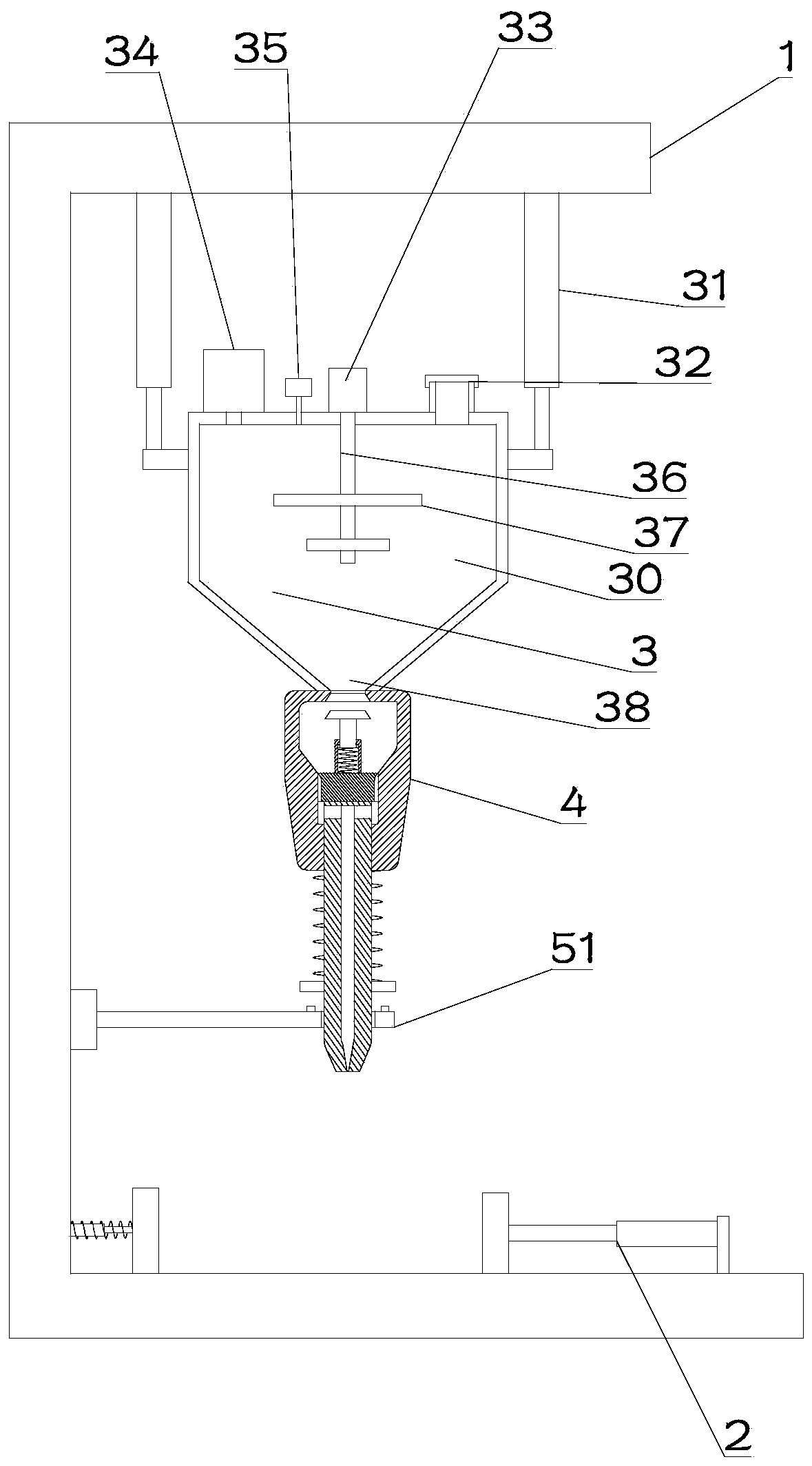
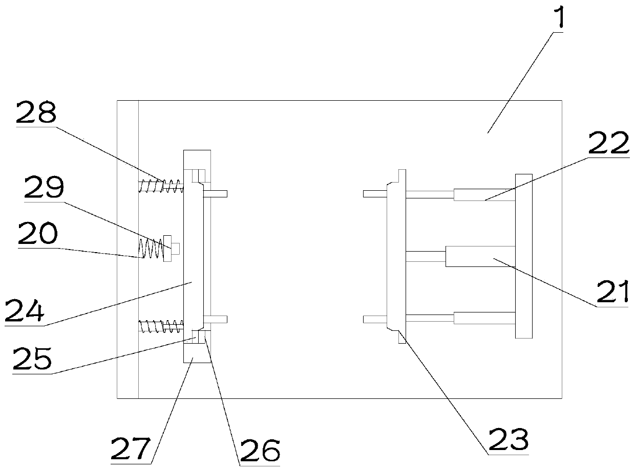
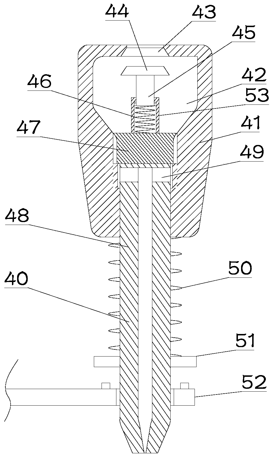
[0023] see Figure 1~2 , in Embodiment 1 of the present invention, a dispensing device for electronic components, including a frame 1, the bottom of the frame 1 is provided with a clamping part 2 for clamping components, and the top of the clamping part 2 is provided with The discharge part 4, the discharge part 4 is installed under the material storage part 3, and the discharge part 4 communicates with the storage part 3, and the storage part 3 is installed on the frame 1; the clamping part 2 Including the A clip 23 and the B clip 24 provided in cooperation with each other, the A clip 23 and the B clip 24 are set for clamping components, and the B clip 24 is arranged on the mounting hole on the mounting part 27, And the two sides of the B clip 24 are provided with an adsorption part 1 25 that cooperates with the adsorption part 2 26 on the mounting part 27, the adsorption part 1 25 and the adsorption part 2 26 are sucked together, and the adsorption part 2 26 is fixedly insta...

Embodiment 2

[0026] see Figure 1~3 The main difference between this embodiment 2 and embodiment 1 is that the storage part 3 includes a storage shell 30 and a B telescopic cylinder 31 connected to the storage shell 30, and the extended end of the B telescopic cylinder 31 is fixedly installed on the On the material storage case 30 , the fixed end is connected to the frame 1 . The B telescopic cylinder 31 is set to provide power for the storage shell 30 to lift up and down.

[0027] A stirring mechanism is arranged inside the storage case 30, which ensures the quality of the glue.

[0028] The storage shell 30 is also provided with a feeding port 32, a pressure gauge 35 and a surge tank 34, and the surge tank 34 is provided to ensure that the internal pressure of the storage shell 30 ensures uniform feeding. A pressure gauge 35 is provided to facilitate observation of the internal pressure of the storage case 30 .

[0029] Described agitating mechanism comprises agitating shaft 36, agita...


PUM


Abstract

The invention discloses a glue dispensing device for an electronic component, and relates to the technical field of electronic equipment production. The device comprises a frame. A clamping componentused for clamping a component is arranged at the bottom of the frame; a discharging component is arranged above the clamping component; the discharging component is installed under a material storagecomponent; the discharging component is communicated with the material storage component; and the material storage component is installed on the frame. The clamping component comprises a clamping piece A and a clamping piece B which are arranged in a matched mode, wherein the clamping piece B is arranged in an installation hole in an installation piece, and the two sides of the clamping piece B are respectively provided with an adsorption piece 1 matched with an adsorption piece 2 on the installation piece, the adsorption pieces 1 and the adsorption pieces 2 are attracted together, and the adsorption pieces 2 are fixedly installed on the installation piece; the side, away from the clamping piece B, of the clamping piece A is connected to a telescopic cylinder A and a guide rod; and the telescopic cylinder A and the guide rod are fixedly installed on the frame. Components are well protected, and the glue dispensing effect is good.

Description

technical field [0001] The invention relates to the technical field of electronic equipment production, in particular to a dispensing device for electronic components. Background technique [0002] Electronic equipment refers to equipment composed of integrated circuits, transistors, electronic tubes and other electronic components, which use electronic technology (including) software to play a role, including electronic computers, robots controlled by electronic computers, numerical control or program-controlled systems, etc. [0003] Electronic components need to be clamped during the dispensing process, and the cylinder drives the clamp to clamp them during the clamping operation, and there are often operational errors during the operation process, resulting in excessive clamping force causing Components are clamped and damaged, so it is necessary to design a dispensing device for electronic components with protective devices to solve the above technical problems. Conte...

Claims


Application Information

Patent Timeline
Patent Type & Authority Applications(China)
IPC IPC(8): B05C5/02B05C11/10B05C13/02B05C11/00
CPCB05C5/02B05C11/00B05C11/10B05C13/02
Inventor 徐尚
Owner 黄昌宾
Learn More