Material conveying device

A technology for conveying devices and materials, which is applied in the direction of packaging, etc., can solve the problems of affecting the conveying tempo, low arrangement efficiency, and cost, and achieve the effect of stable arrangement effect, high arrangement efficiency and consistent orientation

Inactive Publication Date: 2020-03-27
湖南沃峰智能科技有限公司
View PDF11 Cites 6 Cited by
  • Summary
  • Abstract
  • Description
  • Claims
  • Application Information

AI Technical Summary

Problems solved by technology

[0003] In the process of channel steel production, the channel steel needs to be conveyed, but because the channel steel after production is placed in disorder, it is not conducive to the subsequent same packaging and sorting. In the existing conveying device, it is generally arranged and fed manually, which is more expensive. A lot of manpower, and the arrangement efficiency is low, which affects the delivery rhythm

Method used


Image

  • Material conveying device
  • Material conveying device
  • Material conveying device

Examples


Embodiment 1

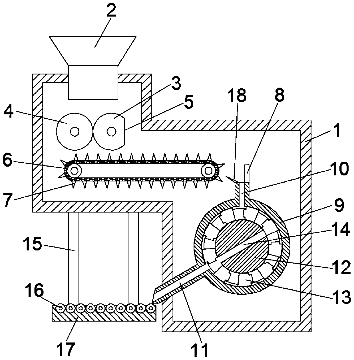
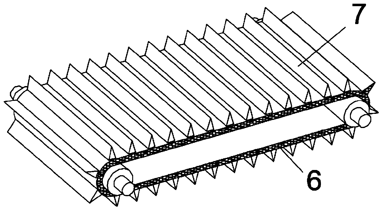
[0021] see figure 1 , a material conveying device, including a housing 1, a feed inlet 2 is opened above the housing 1, and a straightening assembly is arranged below the feeding inlet 2, and the straightening assembly includes a driving roller 3 and a driven roller The roller 4, the driving roller 3 and the driven roller 4 are in the same horizontal plane and are in rolling contact with each other, the cylindrical surface of the driving roller 3 is partially cut off to form a plane 5; a conveyor belt 6 for conveying materials is provided below the centering assembly, The conveying end of the conveyor belt 6 is provided with a turning mechanism;

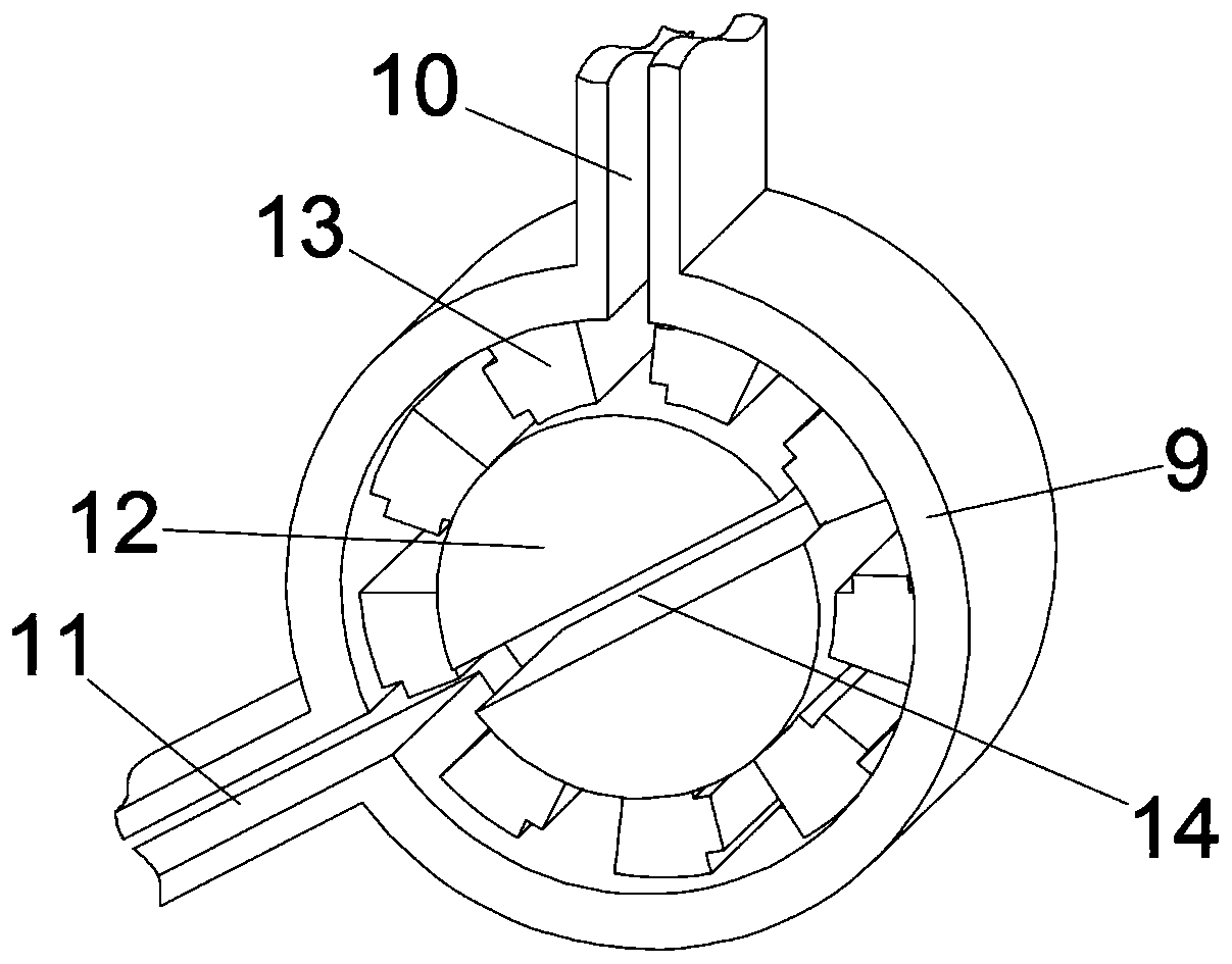
[0022] see figure 2 , the turning mechanism includes a ring 9, a half cylinder 12 and a holding block 13, two half cylinders 12 are fixed inside the ring 9, and an inclined downward chute is formed between the two half cylinders 12 14. A circular channel is formed between the outer cylindrical surface of the semi-cylinder 12 and t...

Embodiment 2

[0033] In order to facilitate the same packaging of the channel steel discharged from the discharge channel 11, this embodiment has been further improved on the basis of embodiment 1. The improvement is: there are several rows and The outlet of the discharge channel 11 is connected to the roller 16 that can roll freely. The bottom of the roller 16 is provided with a mounting seat 17, and the mounting seat 17 is fixed on the shell 1 through the fixing frame 15; After the steel is discharged from the discharge channel 11, it slides onto the drum 16 in sequence, and the operator can pack the channel steel.

[0034] The material conveying device is equipped with a straightening component and a turning mechanism to carry out uniform arrangement while conveying messy and disordered channel steel to ensure that the channel steel at the output end is placed neatly and at the same time in the same direction. Compared with traditional manual arrangement, it greatly saves manpower. , and t...


PUM


Abstract

The invention discloses a material conveying device. The material conveying device comprises a shell, a feeding inlet is formed in the upper part of the shell, and a straightening assembly is arrangedon the lower part of the feeding inlet and comprises a driving idler wheel and a driven idler wheel which are located on the same horizontal plane and are in mutual rolling contact; the cylindrical surface part of the driving idler wheel is cut off to form a plane; and a conveyor belt used for conveying materials is arranged below the straightening assembly, and an overturning mechanism is arranged at the conveying tail end of the conveyor belt and comprises a circular ring, semi-cylinders and a clamping block. The material conveying device is provided with the straightening assembly and theoverturning mechanism to convey disorderly channel steel and meanwhile arrange the channel steel in a unified mode to ensure that the channel steel at the output end is placed in order, meanwhile theorientation is consistent, compared with traditional manual arranging, manpower is saved greatly, the arranging efficiency is high, and the arranging effect is stable.

Description

technical field [0001] The invention relates to the technical field of channel steel production, in particular to a material conveying device. Background technique [0002] Channel steel is a long strip of steel with a groove-shaped cross-section. It belongs to carbon structural steel for construction and machinery. It is a section steel with a complex cross-section. Channel steel is mainly used in building structures, curtain wall engineering, mechanical equipment and vehicle manufacturing. [0003] In the process of channel steel production, the channel steel needs to be conveyed, but because the channel steel after production is placed in disorder, it is not conducive to the subsequent same packaging and sorting. In the existing conveying device, it is generally arranged and fed manually, which is more expensive. It requires a lot of manpower, and the arrangement efficiency is low, which affects the delivery rhythm. Contents of the invention [0004] The object of the...

Claims


Application Information

Patent Timeline
Patent Type & Authority Applications(China)
IPC IPC(8): B65B35/44B65B35/46B65B35/58
CPCB65B35/44B65B35/46B65B35/58
Inventor 刘绍亚吴继春王红辉熊任上王晟垚
Owner 湖南沃峰智能科技有限公司
Why Eureka
Try Eureka