Stacking device for power equipment

A technology for power equipment and mobile devices, applied to cranes, etc., can solve problems such as high requirements for operating space, safety of power equipment damage, and large manpower consumption, so as to achieve low requirements for operating space, reduce workload, and improve work efficiency Effect

Inactive Publication Date: 2020-03-27
RES INST OF ECONOMICS & TECH STATE GRID SHANDONG ELECTRIC POWER +3
View PDF5 Cites 3 Cited by
  • Summary
  • Abstract
  • Description
  • Claims
  • Application Information

AI Technical Summary

Problems solved by technology

[0003] When transporting power equipment, it is necessary to place the power equipment at a designated location and stack the power equipment. The stacked power equipment is usually transported by forklift or crane, and sometimes even the power equipment is transported manually. Using forklift or crane to transport power equipment is often difficult There are very high requirements for space, and the use of manpower to carry power equipment will consume a lot of manpower, which will easily lead to damage to power equipment and there are certain safety hazards

Method used


Image

  • Stacking device for power equipment
  • Stacking device for power equipment
  • Stacking device for power equipment

Examples


Embodiment 1

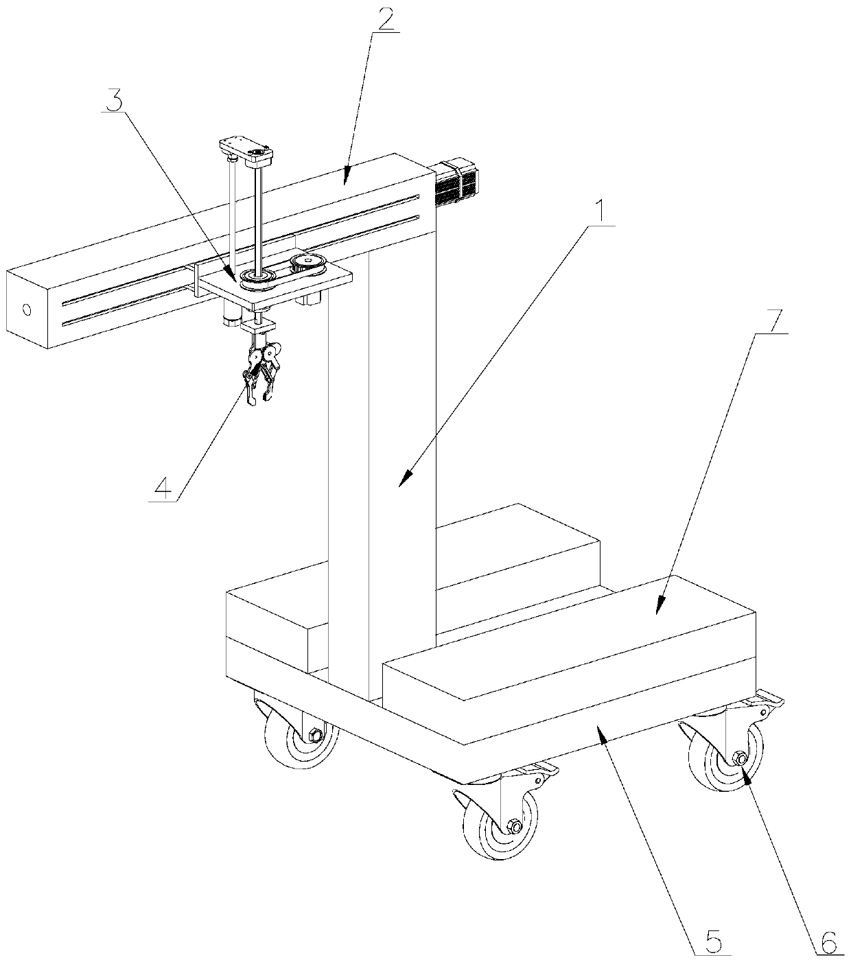
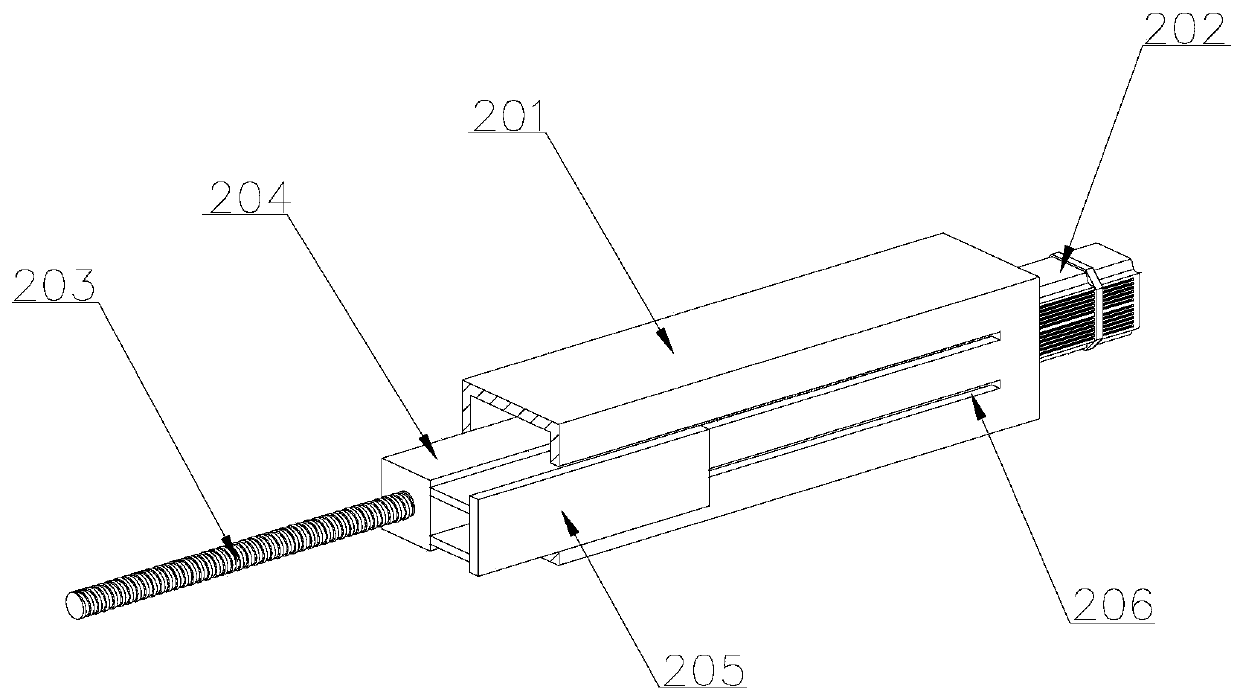
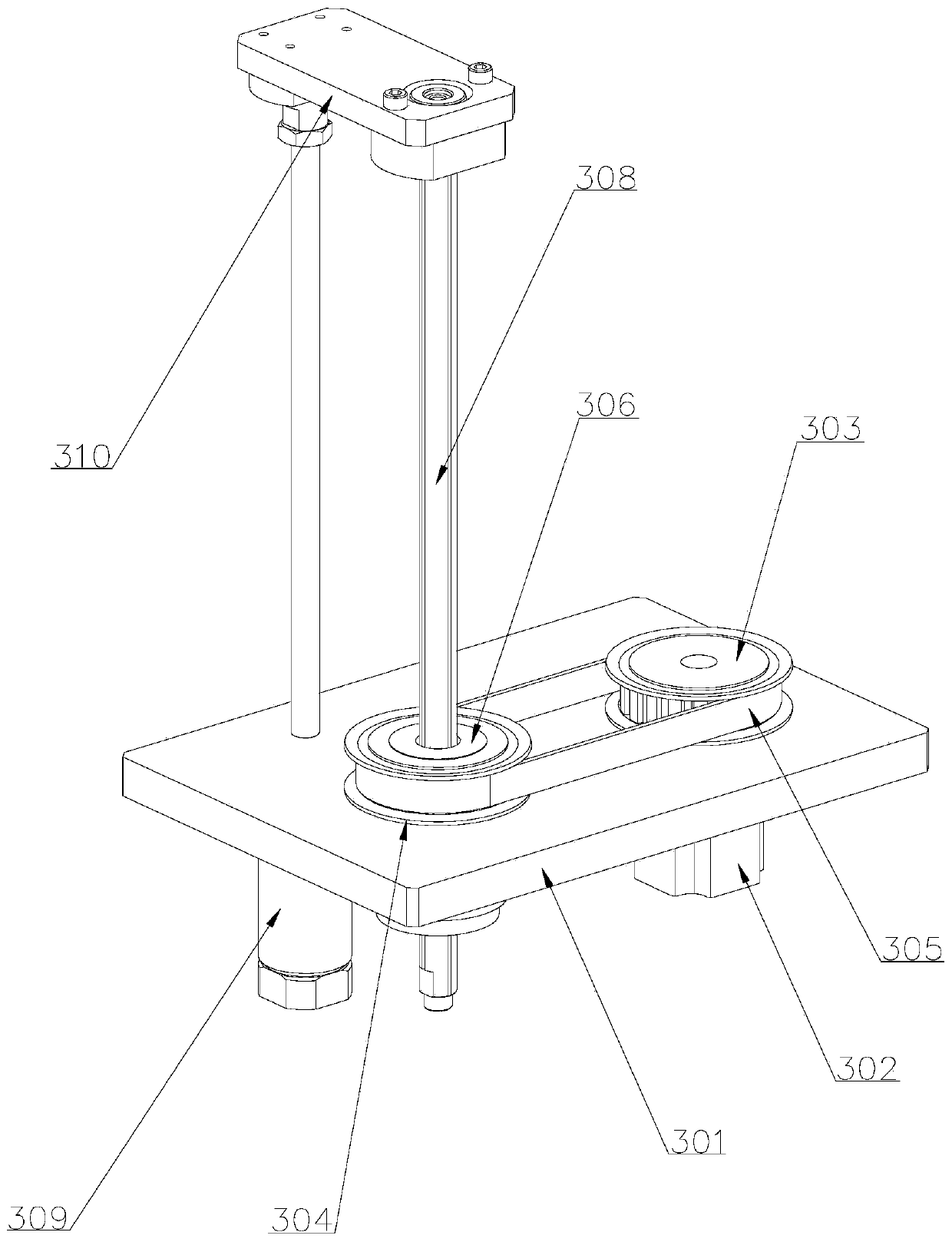
[0031] Such as Figure 1-6As shown, a stacking device for power equipment includes a column 1, a moving device 2, a lifting and rotating device 3, and a clamping device 4. The moving device 2 is arranged on the top of the column 1, and the lifting and rotating device 3 is set On one side of the mobile device 2 and connected with the mobile device 2, the clamping device 4 is arranged at the lower end of the lifting and rotating device 3, and the bottom of the column 1 is provided with a base 5, and the contact area with the ground is increased through the base 5, The stability during work is improved. The base 5 is provided with a counterweight 7 to prevent rollover when the power equipment is heavy and ensure the stability during work. The bottom of the base 5 is provided with a walking wheel 6, It is convenient for the device to move and improves the efficiency of the movement. When stacking the power equipment, the power equipment is clamped and fixed by the clamping device ...

Embodiment 2

[0036] Such as Figure 7 As shown, the difference from Embodiment 1 is that the clamping device 4 includes a top plate 411, a vertical plate 412, a first splint 413, a second electric telescopic rod 414, a third electric telescopic rod 415, and a second splint 416. The top plate 411 is fixed on the bottom of the slide bar 308, the vertical plate 412 is fixed on both sides of the top plate 411, the first splint 413 is set on the inner side of the vertical plate 412, and the second electric telescopic rod 414 is set on the Between the vertical plate 412 and the first splint 413, the second electric telescopic rod 414 is installed on the vertical plate 412, and the movable end of the second electric telescopic rod 414 is connected with the first splint 413, and the third electric telescopic rod 415 is arranged on the first splint 413. The top and the bottom of a splint 413, the second splint 416 is set with the movable end of the third electric telescopic rod 415, and the first s...


PUM


Abstract

The invention discloses a stacking device for power equipment. The stacking device comprises an upright post, a moving device, a lifting rotating device and a clamping device, wherein the moving device is arranged on the top of the upright post; the lifting rotating device is arranged on one side of the moving device and is connected with the moving device; and the clamping device is arranged at the lower end of the lifting rotating device. According to the stacking device, the mobile device and the rotary lifting device can drive the power equipment to move transversely and longitudinally androtate in the circumferential direction, so that the working efficiency of stacking the power equipment is improved, the requirement on the operation space is low, only manual assistance is requiredwhen the power equipment is stacked, the manual workload is greatly reduced, the safety of stacking the power equipment is improved, and potential safety hazards are reduced.

Description

technical field [0001] The invention belongs to the technical field of electric equipment, and in particular relates to a stacking device for electric equipment. Background technique [0002] Power equipment mainly includes two categories: power generation equipment and power supply equipment. Power generation equipment is mainly power plant boilers, steam turbines, gas turbines, water turbines, generators, transformers, etc. Power supply equipment is mainly transmission lines of various voltage levels, transformers, contactors and more. [0003] When transporting power equipment, it is necessary to place the power equipment at a designated location and stack the power equipment. The stacked power equipment is usually transported by forklift or crane, and sometimes even the power equipment is transported manually. Using forklift or crane to transport power equipment is often difficult There are very high requirements for space, and it will consume a lot of manpower to carry...

Claims


Application Information

Patent Timeline
Patent Type & Authority Applications(China)
IPC IPC(8): B66C23/64B66C23/72
CPCB66C23/64B66C23/72
Inventor 杨慧颖朱毅赵红卫李雨彤
Owner RES INST OF ECONOMICS & TECH STATE GRID SHANDONG ELECTRIC POWER
Why Eureka
Try Eureka