Hydraulic lifting cargo elevator

A technology of hydraulic lifting and freight elevator, applied in the direction of lifting frame, lifting device, etc., can solve the problems of no-load waste, inability to protect high-rise goods, cumbersome and other problems, and achieve reasonable carrying capacity, avoid overload risks, and eliminate no-load waste. Effect

Active Publication Date: 2020-03-27
苏州中瑞升降机械有限公司
View PDF19 Cites 3 Cited by
  • Summary
  • Abstract
  • Description
  • Claims
  • Application Information

AI Technical Summary

Problems solved by technology

[0003] However, there are still relatively obvious defects in its use: 1. The limit baffle for protecting the goods in the above-mentioned device is fixed, and its height cannot be adjusted. When the goods are piled up high, the above-mentioned device cannot The high-rise cargo plays an effective protective role, and it is easy to cause the high-rise cargo to fall and be damaged during the lifting process, which poses a large safety hazard; 2. The above-mentioned device cannot measure the height of the cargo stack in time during the cargo loading process, and can only Visual observation, but manual observation has a large error. If the stacking height is too high, it may not be able to pass through the transfer channel or the shelf is too small to be completely transferred. If the stacking height is far lower than the passable standard, it will cause waste of empty load. ; 3. The above-mentioned devices lack a device for timely measurement of the cargo load. Often, the cargo is weighed first and then transported, or weighed after receiving the cargo.

Method used


Image

  • Hydraulic lifting cargo elevator
  • Hydraulic lifting cargo elevator
  • Hydraulic lifting cargo elevator

Examples


Embodiment Construction

[0022] The technical solutions in the embodiments of the present invention will be clearly and completely described below in conjunction with the accompanying drawings in the embodiments of the present invention. Obviously, the described embodiments are only a part of the embodiments of the present invention, rather than all the embodiments. Based on the embodiments of the present invention, all other embodiments obtained by those of ordinary skill in the art without creative work shall fall within the protection scope of the present invention.

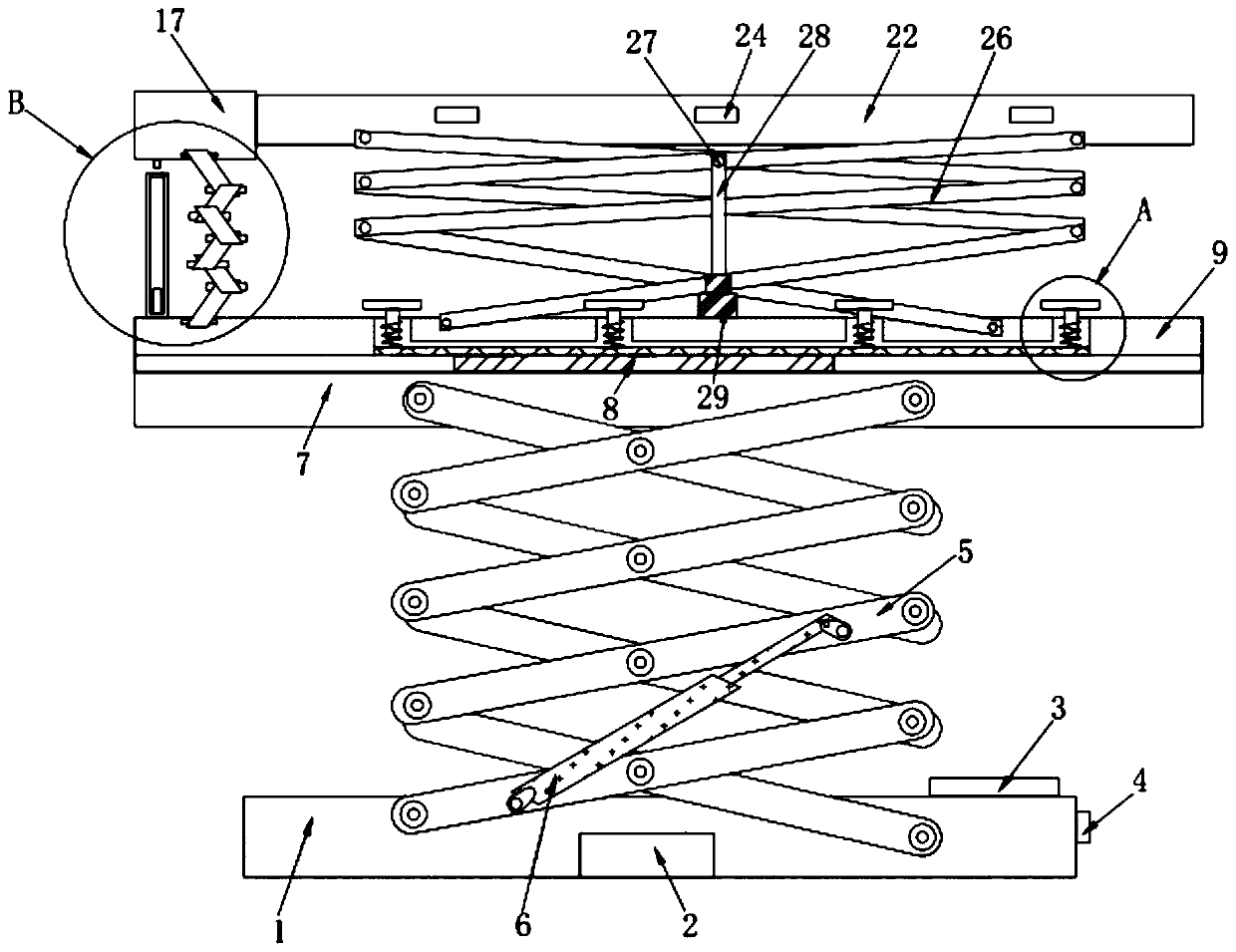
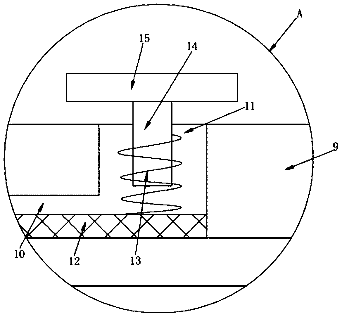
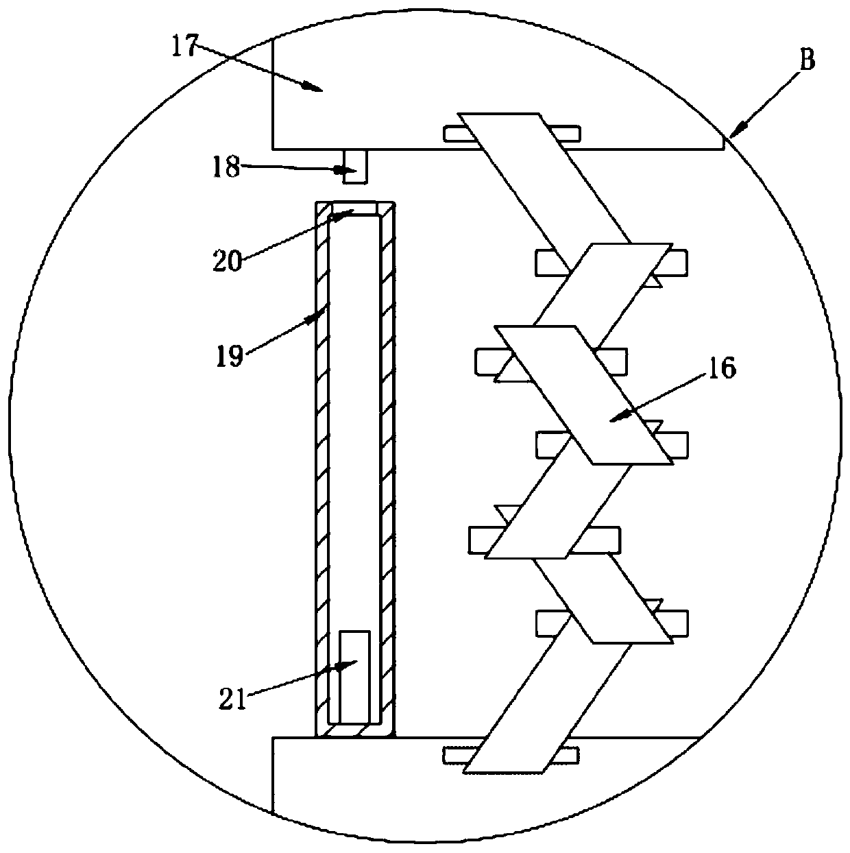
[0023] See Figure 1-4 , The present invention provides a technical solution:

[0024] A hydraulic lift freight elevator includes a base 1, and a PLC controller 2 is arranged in the inner cavity of the base 1. The PLC controller 2 can adopt the FX1N-40MR-001 model provided by Mitsubishi brand. The surface of the base 1 is provided with a display board 3. The display board 3 is used to display the height and weight information of the goods...


PUM


Abstract

The invention discloses a hydraulic lifting cargo elevator. The hydraulic lifting cargo elevator comprises a base; a shear-fork type supporting frame is arranged on the base in a hinged manner; the shear-fork type supporting frame is hinged to two ends of the hydraulic cylinder; a pressure sensor is arranged on the bottom plate of a lifting table; an infrared range finder is fixedly arranged on one side, close to an upper plate of the lifting table, of a vertical side baffle rod; a plurality of groups of infrared sensor transmitters are arranged on one side, close to a second transverse side baffle rod, of a first transverse side baffle rod; a plurality of groups of infrared sensor receivers are correspondingly arranged on one side, close to the first transverse side baffle rod, of the second transverse side baffle rod; and a transverse side shear-fork type protective rail is arranged on each of the sides, close to the upper plate of the lifting table, of the first transverse side baffle rod and the second transverse side baffle rod in the hinged manner. The invention provides the hydraulic lifting cargo elevator; and the height of a cargo protecting device can be automatically adjusted according to the stacking height of cargo, and the stacking height and the cargo quality of the cargo on the cargo elevator are fed back in time, so that the hydraulic lifting cargo elevator isconvenient for a user to understand situations and make an adjustment, and is more accord with various situations in actual use.

Description

Technical field [0001] The invention relates to the technical field of hydraulic freight elevators, in particular to a hydraulic freight elevator. Background technique [0002] In the prior art, a fixed scissor-type hydraulic freight elevator with the application number "201721885042.3" is equipped with limit buffer piles vertically at the four corners of the base. The limit buffer pile is composed of a floating end, a fixed sleeve and a spring. The floating end The bottom is sleeved with a spring and inserted vertically from the top center of the fixed sleeve. The inner side of the frame at the front and rear of the base is provided with sliding grooves. Sliders are installed in the sliding grooves. The sliding blocks are hinged to the bottom right end of the scissor support arm and the bottom right end of the scissor support arm. A connecting plate is also hinged, an internal threaded through hole is opened in the middle of the connecting plate, and a lead screw is penetrated i...

Claims


Application Information

Patent Timeline
Patent Type & Authority Applications(China)
IPC IPC(8): B66F7/08B66F7/28
CPCB66F7/0666B66F7/08B66F7/28
Inventor 陈琪
Owner 苏州中瑞升降机械有限公司
Why Eureka
Try Eureka