A method for diagnosing the health state of a liquid reductant supply pump

A technology of health status and supply pump, which is applied in the direction of exhaust gas treatment device diagnostic device, pump test, liquid variable capacity machinery, etc., which can solve the lack of individual product diagnosis, limit the application range of diagnostic algorithms, and lack of fault predictability and other problems, achieve the frequency and reliability of diagnosis, overcome the strict requirements of product consistency, and improve the effect of diagnosis reliability

Active Publication Date: 2021-12-07
KAILONG HIGH TECH
View PDF7 Cites 0 Cited by
  • Summary
  • Abstract
  • Description
  • Claims
  • Application Information

AI Technical Summary

Problems solved by technology

[0003] The system health status diagnosis method provided by the current selective catalytic reduction system usually monitors the basic work function of the supply pump. When the supply pump fails, the OBD (On Board Diagnosis) system of the diesel engine issues a fault report and performs torque limit or shutdown operations. Lack of certain failure predictability, that is, the system does not give users a reminder during the long-term running period when the system transitions from aging to failure. The supply pump failure reported by the OBD system is sometimes caused by very simple reasons. However, if the user sends the vehicle to the after-sales service center for processing, it will be time-consuming and labor-intensive; in addition, the existing supply pump diagnosis method usually uses the same diagnosis method and diagnosis threshold and lacks individualized diagnosis of a single product. In large-scale industrial production, due to manufacturing and assembly errors, there are certain differences in the characteristics of a single supply pump. Using the same diagnostic threshold may lead to misjudgment or missed judgment of faults, which limits the effectiveness of existing diagnostic algorithms to a certain extent. Application range

Method used


Image

  • A method for diagnosing the health state of a liquid reductant supply pump
  • A method for diagnosing the health state of a liquid reductant supply pump
  • A method for diagnosing the health state of a liquid reductant supply pump

Examples


Embodiment Construction

[0027] The present invention will be further described below in conjunction with drawings and embodiments. It should be understood that the specific embodiments described here are only used to explain the present invention, but not to limit the present invention. In addition, it should be noted that, for ease of description, only part of the present invention is shown in the accompanying drawings but not all of the content. Unless otherwise defined, all technical and scientific terms used herein are related to the technical field of the present invention. The skilled person generally understands the same meaning. The terms used herein are for describing specific embodiments only, and are not intended to limit the present invention.

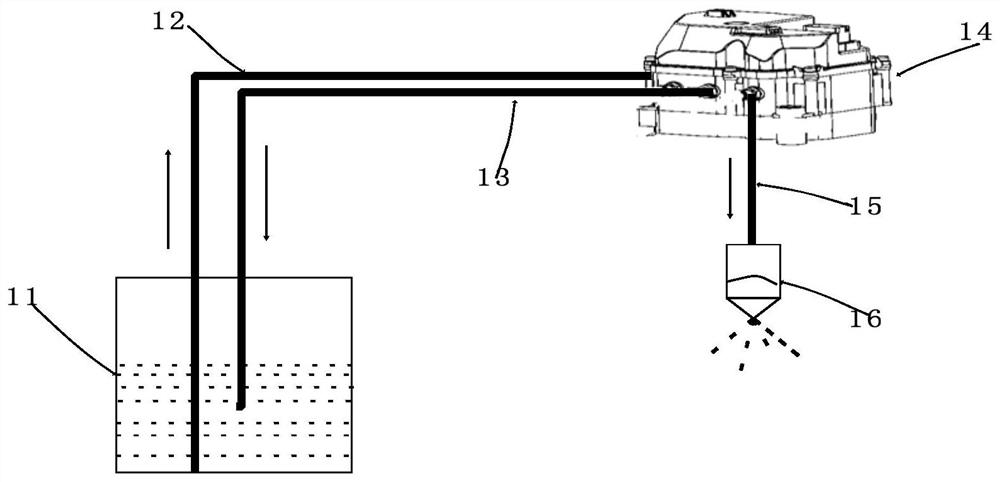
[0028] like figure 1 As shown, the structure of diesel engine post-treatment urea injection system components includes urea tank 11, urea suction pipe 12, urea return pipe 13, liquid reductant supply pump, that is, urea supply pump 14, urea solu...


PUM


Abstract

The invention discloses a method for diagnosing the health state of a liquid reductant supply pump, which includes the following steps: S101. Calculating the standard control parameter threshold for determining the healthy state according to the power supply voltage of the supply pump when the calculation condition is satisfied; S102. The working state of the supply pump meets the design requirements. Calculate the control parameters that can characterize its actual health state when the conditions are determined; S103. Determine the actual health of the supply pump according to the deviation between the actual health state control parameters of the supply pump calculated in step S102 and the standard control parameter threshold value calculated in step S101. Status; S104. Determine the cause of the failure according to the actual health status of the supply pump calculated in step S103 and the deviation of the health control parameters, and report to the supply pump control unit. The invention can monitor the health state of the reductant supply pump in real time, and the diagnosis is reliable without adding extra cost.

Description

technical field [0001] The invention relates to the technical field of aftertreatment of internal combustion engines, in particular to a method for diagnosing the health state of a liquid reductant supply pump. Background technique [0002] Vehicle systems include vehicles powered by diesel engines. Diesel engines occupy an absolute dominance in the field of commercial vehicles due to their low fuel consumption and strong power. However, the particulate pollutants PM and toxic gas components NOx emitted by them have always been criticized. . With the continuous upgrading of diesel vehicle emission requirements in my country, selective catalytic reduction system (SCR) has become the standard configuration of diesel engine exhaust treatment system, in which the reductant supply pump plays a basic role as the core component of the SCR system, which is responsible for the liquid reductant (Ammonia water or urea) is absorbed from the storage tank, raised to the set pressure and m...

Claims


Application Information

Patent Timeline
Patent Type & Authority Patents(China)
IPC IPC(8): F01N11/00F04B51/00
CPCF01N11/00F01N2550/05F01N2610/02F04B51/00Y02T10/40
Inventor 臧志成曾伟马超马涛董孝虎
Owner KAILONG HIGH TECH
Why Eureka
Try Eureka