Heat energy recovery device and heat energy recovery process for dyeing waste liquid

A technology of heat energy recovery and dyeing waste liquid, applied in heat recovery systems, indirect heat exchangers, energy-saving heating/cooling, etc., can solve problems such as resource waste, save energy, save time and energy, and reduce waste.

Active Publication Date: 2020-03-27
山东明福染业有限公司
View PDF9 Cites 1 Cited by
  • Summary
  • Abstract
  • Description
  • Claims
  • Application Information

AI Technical Summary

Problems solved by technology

[0004] In the specific use process, the waste liquid in the tank is passed into the chamber, the heat exchange assembly is arranged in the chamber, and the first chamber and the second chamber are respectively provided with a clean water inlet and a clean water outlet , by passing clean water into it, the temperature of the clean water can be raised to a certain extent, and the heat energy can be recycled. However, when the dye liquor in the dyeing box is drawn out, all the dye liquor needs to be drawn out, and there is still The amount of dye contained in some dyeing liquors is sufficient, which is the same as the content of dyes in the required dyeing liquors, and can be used continuously. Extracting them will cause unnecessary waste of resources

Method used


Image

  • Heat energy recovery device and heat energy recovery process for dyeing waste liquid
  • Heat energy recovery device and heat energy recovery process for dyeing waste liquid
  • Heat energy recovery device and heat energy recovery process for dyeing waste liquid

Examples


Embodiment

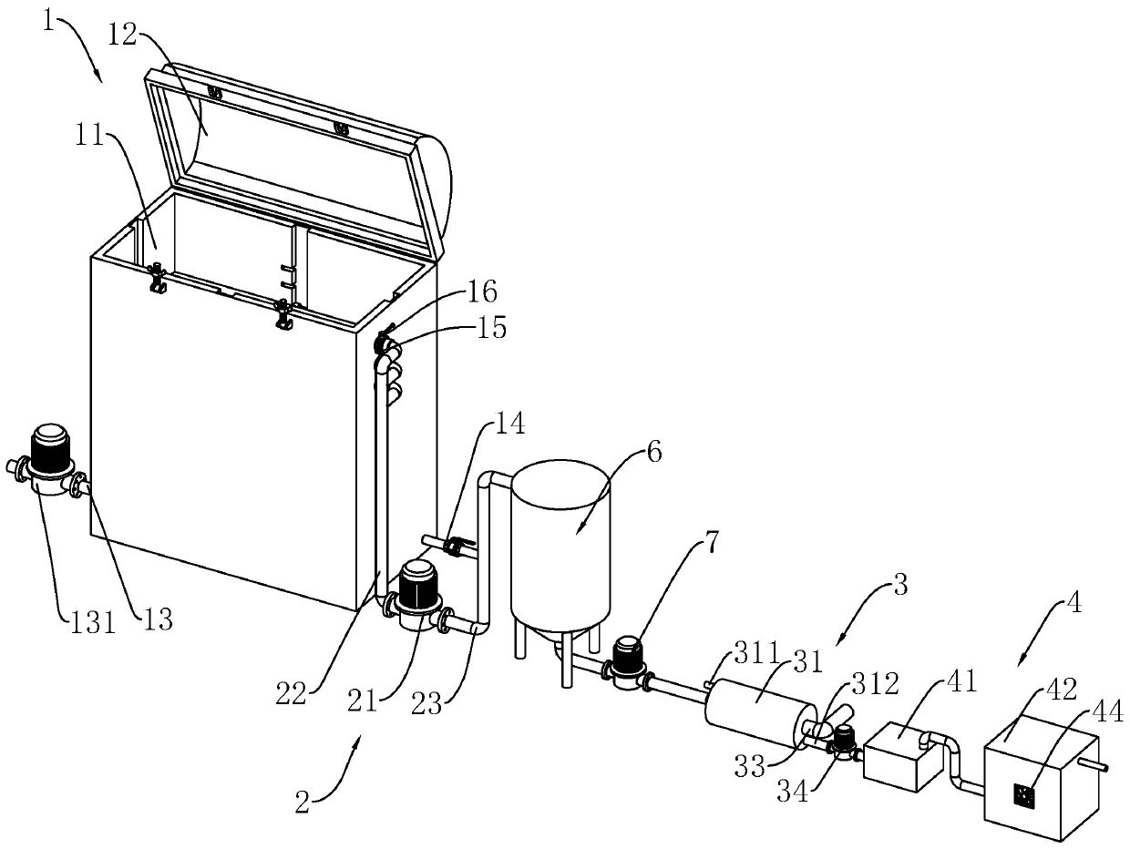
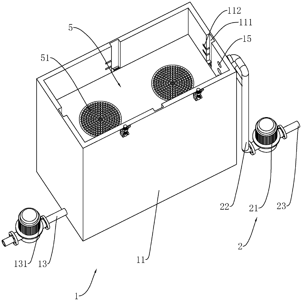
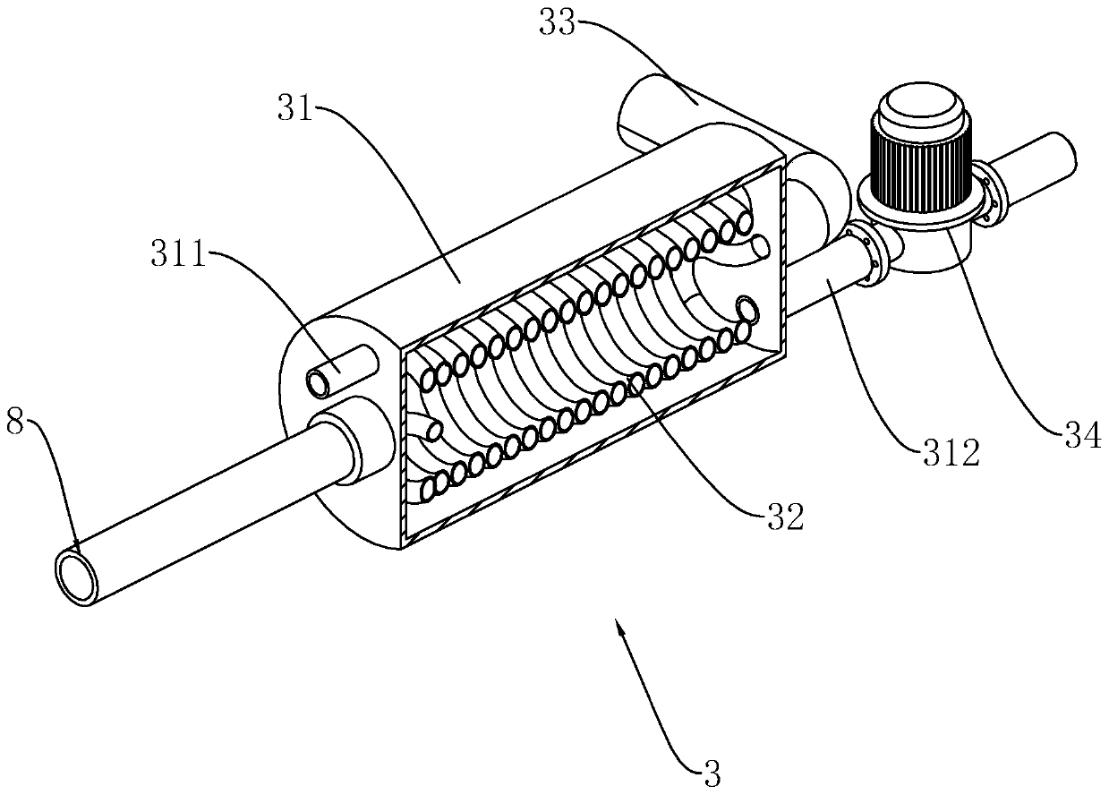
[0051] refer to figure 1 , a heat energy recovery device for dyeing waste liquid, including a dyeing box 1, a liquid pumping assembly 2, a heat exchange assembly 3 and a drying assembly 4; the dyeing box 1 is arranged on the ground to hold the dyeing liquid and dye the skein The liquid pumping assembly 2 is arranged on one side of the dyeing box 1, and its liquid inlet port communicates with the interior of the dyeing box 1 to extract the dye solution in the dyeing box 1; the heat exchange assembly 3 is arranged on one side of the pumping assembly 2 side, which communicates with the water outlet end of the pumping assembly 2, and passes water at normal temperature into the heat exchange assembly 3 to exchange heat with the high-temperature waste liquid, heats up the normal-temperature water, and recycles the heat energy in the high-temperature waste liquid; The drying component 4 is arranged on one side of the heat exchanging component, and it communicates with the heat exchan...


PUM


Abstract

The invention relates to a heat energy recovery device and a heat energy recovery process for dyeing waste liquid. The heat energy recovery device comprises a dyeing box, a liquid pumping assembly, acontainer, a heat exchange assembly and a drying assembly, wherein the liquid pumping assembly is arranged on the outer side of the dyeing box, and the liquid inlet end of the liquid pumping assemblycommunicates with the interior of the dyeing box; the container communicates with the liquid outlet end of the liquid pumping assembly; the heat exchange assembly communicates with the interior of thecontainer; the drying assembly communicates with the heat exchange assembly; the dyeing box comprises a box body and a box cover; a partition plate is arranged in the box body, the partition plate isdetachably connected with the box body, a through hole is formed in the partition plate, and a filter layer is arranged at the position of the through hole; a liquid through hole is formed in the position, positioned on the upper side of the partition plate, of the side wall of the box body, and the liquid inlet end of the liquid pumping assembly communicates with the liquid through hole; a feeding port is formed in the lower end of the side wall of the box body; and a liquid discharging valve is further arranged at the lower end of the side wall of the box body. According to the heat energyrecovery device and the heat energy recovery process, the dyeing waste liquid in the dyeing box can be extracted in a distinguished mode, part of the dyeing liquid with enough dye content is left in the dyeing box to be continuously used, and the waste of resources is reduced.

Description

technical field [0001] The invention relates to a heat energy recovery technology, in particular to a heat energy recovery device and heat energy recovery process for dyeing waste liquid. Background technique [0002] In the production process of the skein yarn, the skein yarn needs to be dyed. The traditional dyeing process adopts the method of heating up dyeing. In the dyeing container, dye and water are added according to the ratio, and dyeing aids are added to it. Dyeing of skeins; after dyeing a batch of skeins, it is necessary to re-proportion the dyes, discharge the original dye solution, and directly discharge it into the sewer, which will cause environmental pollution, and its temperature is high, directly discharge will cause pollution. Indirectly increase the cost, the heat energy recovery device is a device that recycles the heat energy of the discharged waste liquid. [0003] The existing authorized announcement number is CN201864945U patent document discloses ...

Claims


Application Information

Patent Timeline
Patent Type & Authority Applications(China)
IPC IPC(8): F28D21/00
CPCF28D21/00Y02B30/56
Inventor 王室海田明洋郝兆生
Owner 山东明福染业有限公司
Why Eureka
Try Eureka