
Optical imaging lens

An optical imaging lens and imaging technology, applied in optics, optical components, instruments, etc., can solve problems such as unfavorable thinning of mobile phones, digital cameras and automotive lenses, and achieve good imaging quality, large field of view, and small aperture value. Effect

Pending Publication Date: 2020-03-27
GENIUS ELECTRONICS OPTICAL XIAMEN
View PDF2 Cites 6 Cited by
  • Summary
  • Abstract
  • Description
  • Claims
  • Application Information

AI Technical Summary

Problems solved by technology

With the increase in the number of optical lenses, the larger distance on the optical axis from the object side of the first lens to the imaging surface will be unfavorable for the thinning of mobile phones, digital cameras and automotive lenses.

Method used


Image

  • Optical imaging lens
  • Optical imaging lens
  • Optical imaging lens

Examples


Embodiment Construction

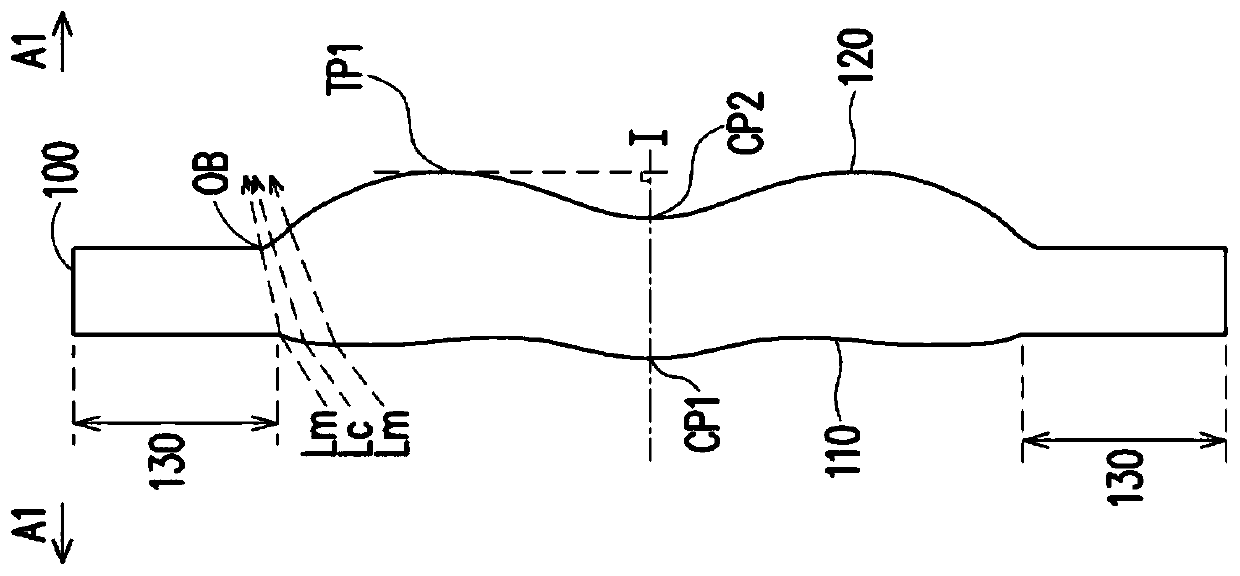
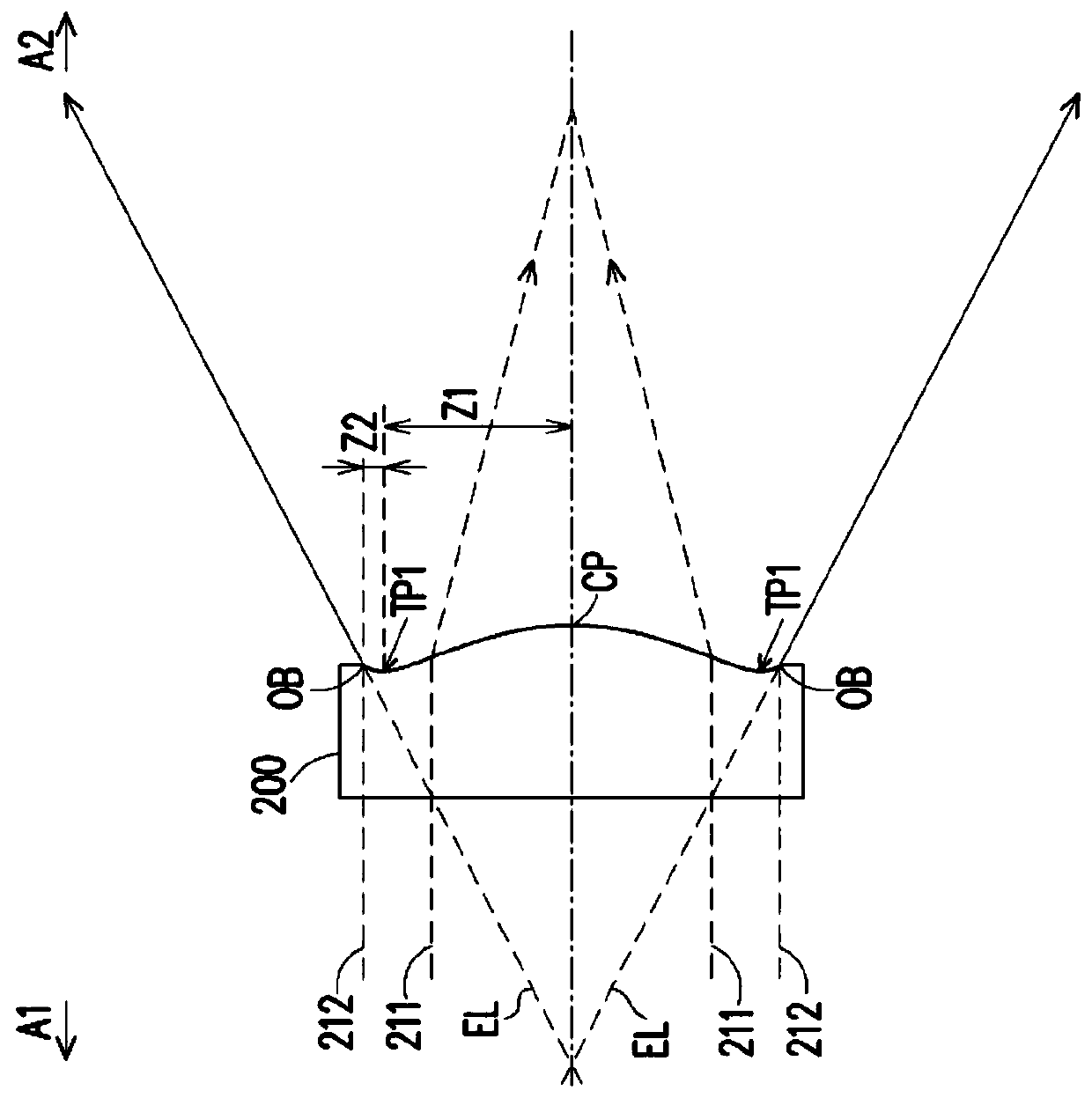
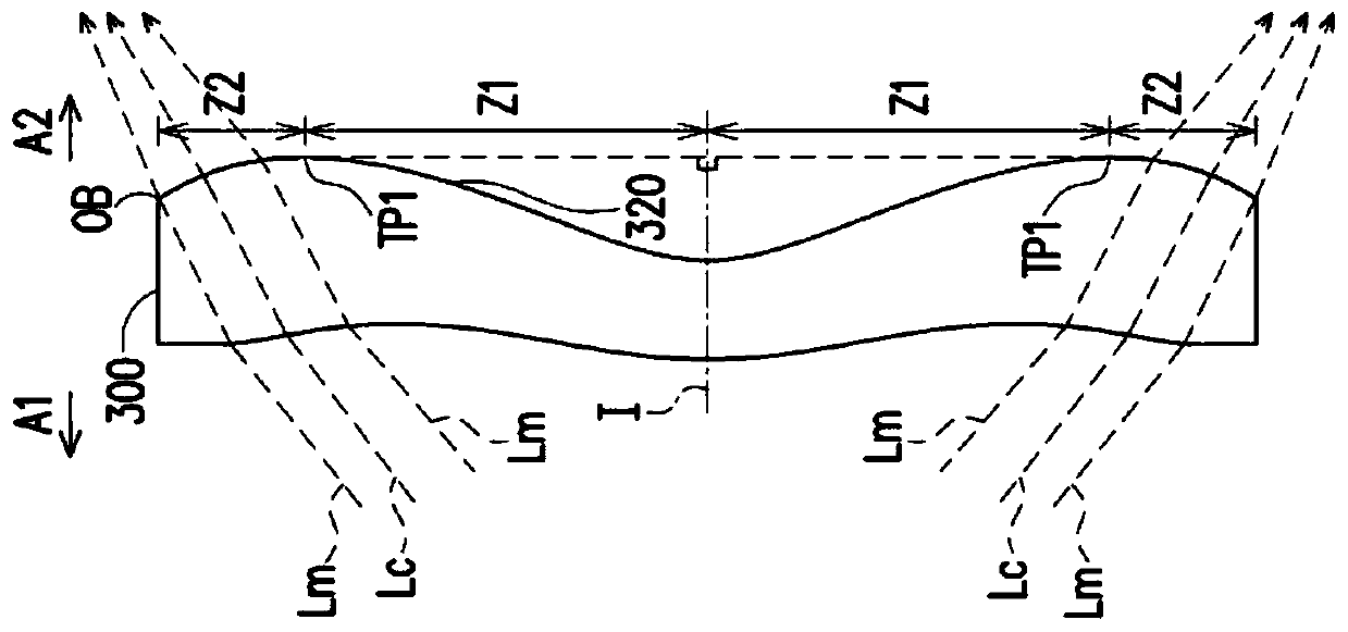
[0038] Before starting to describe the present invention in detail, first clearly indicate the symbols in the drawings: 0: aperture; 1: first lens; 2: second lens; 3: third lens; 4: fourth lens; 5: fifth Lens; 6: sixth lens; 7: seventh lens; 8: eighth lens; 9: optical filter; 10: optical imaging lens; 15, 25, 35, 45, 55, 65, 75, 85, 95, 110, 410, 510: object side; 16, 26, 36, 46, 56, 66, 76, 86, 96, 120, 320: image side; 99: image plane; 100, 200, 300, 400, 500: lens ;130: assembly department; 151, 161, 251, 261, 351, 361, 451, 461, 551, 561, 651, 661, 751, 761, 851, 861, Z1: optical axis area

[0039] 153, 163, 253, 263, 353, 363, 453, 463, 553, 563, 653, 663, 753, 763, 853, 863, Z2: Circumferential area; 211, 212: Parallel rays; A1: Object side; A2 : image side; CP: center point; CP1: first center point; CP2: second center point; EL: extension line; I: optical axis; Lm: marginal ray; Lc: chief ray; M, R: intersection point; OB: optical boundary; TP1: first transition point...


PUM


Abstract

An optical imaging lens sequentially comprises a first lens, a second lens, a third lens, a fourth lens, a fifth lens, a sixth lens, a seventh lens and an eighth lens from an object side to an image side along an optical axis. Each of the first to eighth lenses comprises an object side surface facing the object side and allowing imaging light to pass therethrough and an image side surface facing the image side and allowing imaging light to pass therethrough. The first lens has a positive refractive index. The second lens has a negative refractive index. The optical axis area of the object sidesurface of the fifth lens is a concave surface. The optical axis area of the object side surface of the sixth lens is a convex surface. The optical axis area of the image side surface of the seventhlens is a convex surface. The lens with refractive index of the optical imaging lens is only the first lens to the eighth lens. The lens of the optical imaging lens has a small aperture value, a shortsystem length and a large field angle, and can still maintain good imaging quality.

Description

technical field [0001] The invention relates to the field of optical imaging, in particular to an optical imaging lens. Background technique [0002] In recent years, the optical imaging lens has been continuously evolving, and the number of optical lenses is used to modify problems such as aberration and dispersion to achieve higher and higher imaging quality requirements. With the increase in the number of optical lenses, the larger distance on the optical axis from the object side of the first lens to the imaging surface will be unfavorable for the thinning of mobile phones, digital cameras and automotive lenses. Therefore, designing an optical imaging lens with good imaging quality, light weight and small size has always been the development goal of the design. In addition, a small aperture value is beneficial to increase the luminous flux, and a large field of view is gradually becoming a market trend. How to design an optical imaging lens with a small aperture value ...

Claims


Application Information

Patent Timeline
Patent Type & Authority Applications(China)
IPC IPC(8): G02B13/00G02B13/18
CPCG02B13/0015G02B13/0045G02B9/64
Inventor 朱清智张兰兰廖华滨
Owner GENIUS ELECTRONICS OPTICAL XIAMEN
Learn More