Supercharge Your Innovation With Domain-Expert AI Agents!

Method for correcting scanning errors in shutle type of scanner

A scanner and error technology, applied in the field of reciprocating scanners, can solve the problems of inability to accurately adjust the scanning head, complicated scanner manufacturing, and reduced scanner productivity.

Inactive Publication Date: 2003-05-21
SAMSUNG ELECTRONICS CO LTD
View PDF0 Cites 0 Cited by
  • Summary
  • Abstract
  • Description
  • Claims
  • Application Information

AI Technical Summary

Problems solved by technology

But the distance error with the band is ignored
[0009] When the operator adjusts the scanning head by manipulating the control screw to correct the error of the tilt of the graphic data, there is a problem that the scanning head cannot be adjusted precisely
In addition, there is a disadvantage that since a separate control screw and control sawtooth (zig) are required to correct the inclination error of the graphic data, this complicates the production of the scanner and also reduces the productivity of the production of the scanner.
[0010] In addition, due to the neglect of the error of the distance of the belt, the printing quality is also reduced.

Method used


Image

  • Method for correcting scanning errors in shutle type of scanner
  • Method for correcting scanning errors in shutle type of scanner
  • Method for correcting scanning errors in shutle type of scanner

Examples


Embodiment Construction

[0051] Hereinafter, a method of correcting scanning errors in a scanner according to the present invention will be described in detail with reference to the accompanying drawings.

[0052] Like reference numerals designate like elements. In addition, descriptions of well-known contents in the drawings will be omitted.

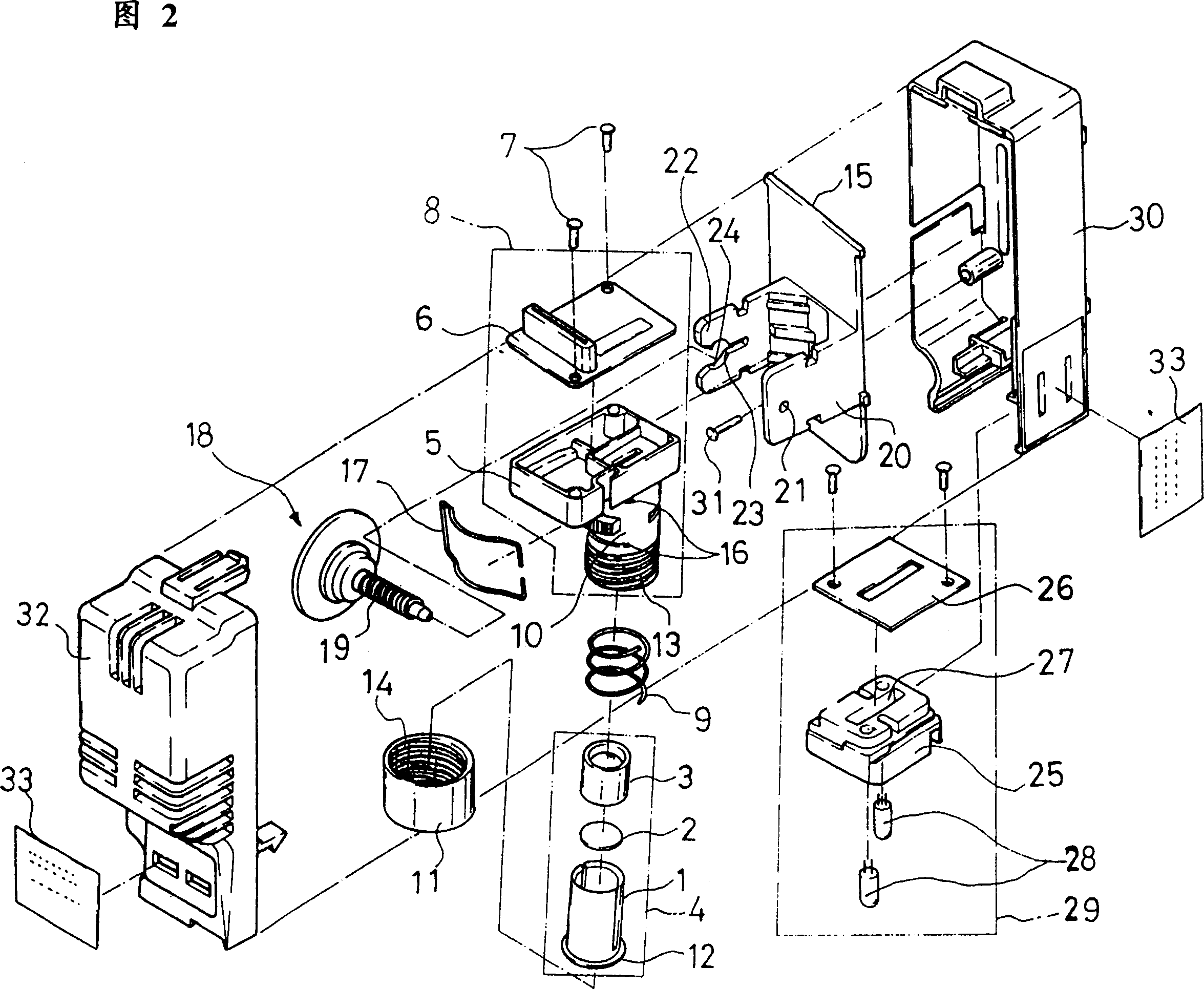
[0053] Fig. 2 is an exploded perspective view of the reciprocating scanning module of the present invention.

[0054]The operation of assembling such a scanning module will be briefly described below. The lens assembly 4 is assembled by inserting the optical filter 2 into the lens holder 1 and then inserting the lens 3 therein sequentially, and then the optical filter 2 and the lens 3 are fixed on the lens holder 1 by fusing. The charge-coupled device assembly 8 is made by fixing the charge-coupled device board 6 into the frame 5 with fixing members 7 such as bolts. After placing the spring 9 on the peripheral surface of the lens holder 1, the lens assembly ...


PUM


Abstract

A method for correcting scanning errors in a shuttle scanner is described. A pattern sheet on which pattern data having a specified shape are recorded is scanned. Errors for incline of the pattern data are corrected by using pattern data of a straight line form among the scanned pattern data having the specified shape. Then, errors for distance between bands are corrected by using pattern data of a specified shape. Accordingly, since the errors for incline and the errors for distance between the bands can be corrected by using a computer program, correcting the errors of the pattern data is very simple. Furthermore, even if the scanner is subjected to an impact from an exterior, correcting the errors for incline and the errors for distance between the bands can be promptly performed.

Description

technical field [0001] The present invention relates to reciprocating scanners, and more particularly, to a method of correcting scanning errors in reciprocating scanners, in which errors in the inclination of graphic data are measured and corrected, and interval errors between bands are detected , so that the transmission distance of the file is corrected. Background technique [0002] Generally speaking, a reciprocating scanner is an instrument with a scanning head mounted on a guide shaft in a reciprocating manner. The shaft is usually arranged in the direction of transferring documents. Graphics on said file. The scanner also includes a lamp assembly having a lamp that projects light onto a graphic on the document; a lens assembly having a lens that converges light reflected from the document; a charge coupled device assembly having a A charge-coupled device converts the reflected light converged by the lens into an electrical signal, the lens assembly includes a filte...

Claims


Application Information

Patent Timeline
IPC IPC(8): H04N1/04G06K7/10H04N1/047H04N1/12H04N1/191
CPCH04N1/128H04N1/047H04N2201/04756H04N2201/04787H04N1/12H04N2201/04703H04N1/1911H04N2201/04717H04N2201/04734H04N2201/04793G06K7/10
Inventor 尹暎重河钟浩
Owner SAMSUNG ELECTRONICS CO LTD
Features
  • R&D
  • Intellectual Property
  • Life Sciences
  • Materials
  • Tech Scout
  • Unparalleled Data Quality
  • Higher Quality Content
  • 60% Fewer Hallucinations
Learn More