Method and device for determining rotor angle position of permanent magnet synchronous motor and motor

A permanent magnet synchronous motor, rotor angle technology, applied in the direction of electronic commutator, etc., can solve the problem that the low-speed control occasion cannot meet the application requirements, etc.

Active Publication Date: 2020-03-27
GUANGDONG WELLING ELECTRIC MACHINE MFG +1
View PDF11 Cites 2 Cited by
  • Summary
  • Abstract
  • Description
  • Claims
  • Application Information

AI Technical Summary

Problems solved by technology

It can be seen that the position resolution of the permanent magnet synchronous motor Hall position acquisition scheme in the related art is 60° electrical angle, which cannot meet the application requirements for high-demand low-speed control occasions

Method used


Image

  • Method and device for determining rotor angle position of permanent magnet synchronous motor and motor
  • Method and device for determining rotor angle position of permanent magnet synchronous motor and motor
  • Method and device for determining rotor angle position of permanent magnet synchronous motor and motor

Examples


Embodiment Construction

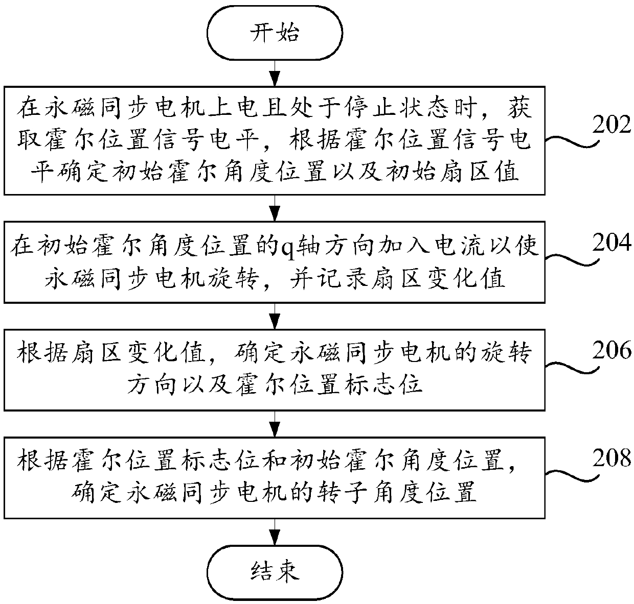
[0037] In order to understand the above-mentioned purpose, features and advantages of the present invention more clearly, the present invention will be further described in detail below in conjunction with the accompanying drawings and specific embodiments. It should be noted that, in the case of no conflict, the embodiments of the present invention and the features in the embodiments can be combined with each other.

[0038] In the following description, many specific details are set forth in order to fully understand the present invention, but the present invention can also be implemented in other ways different from those described here, therefore, the protection scope of the present invention is not limited to the specific details disclosed below. EXAMPLE LIMITATIONS.

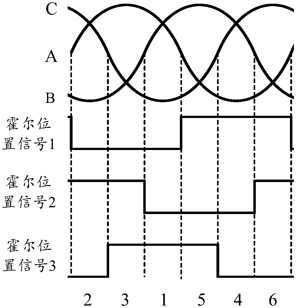
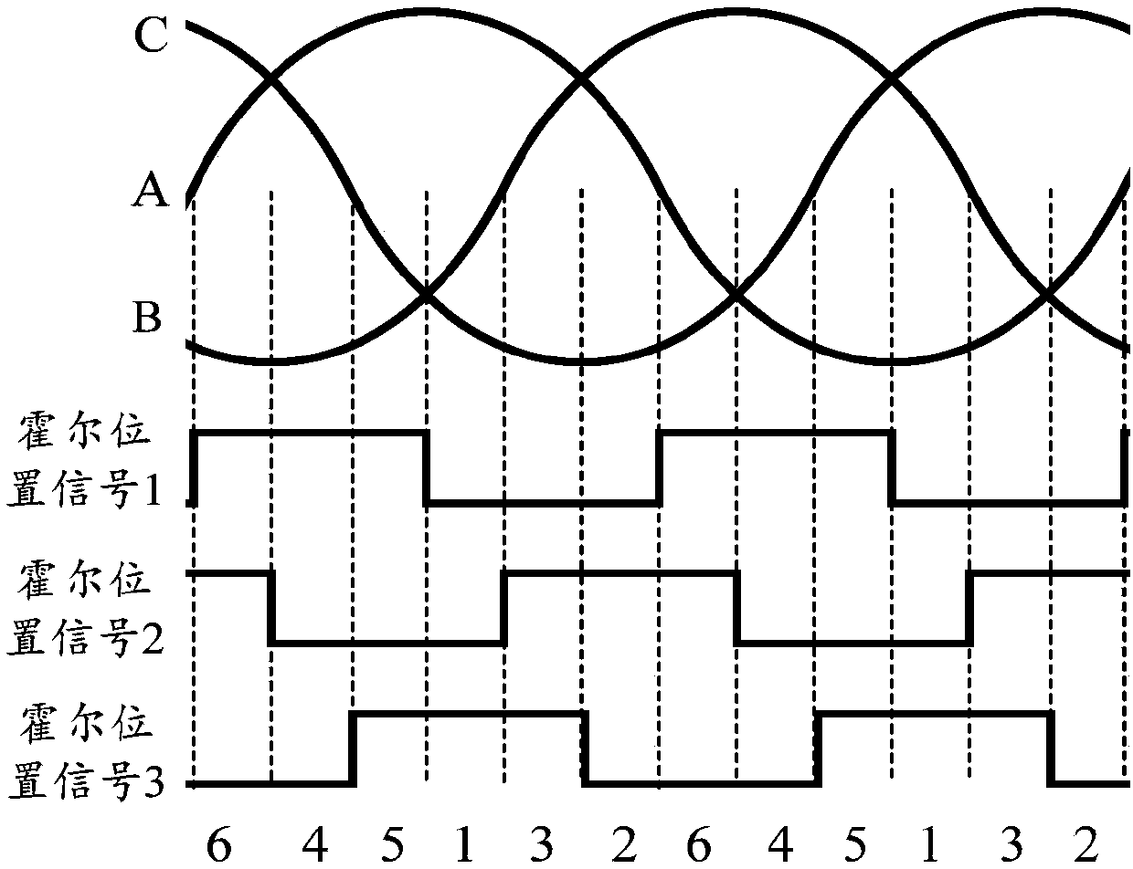
[0039] The embodiment of the first aspect of the present invention proposes a method for determining the angular position of the rotor of a permanent magnet synchronous motor. The permanent magnet synchrono...


PUM


Abstract

The invention provides a method and device for determining the rotor angle position of a permanent magnet synchronous motor and the permanent magnet synchronous motor. The permanent magnet synchronousmotor is provided with a plurality of Hall position sensors. The number of pole pairs of the Hall magnetic ring is twice that of the pole pairs of the permanent magnet synchronous motor; the Hall position sensors are used for outputting Hall position signals, and the method comprises the steps: obtaining a Hall position signal level when the permanent magnet synchronous motor is powered on and isin a stop state, and determining an initial Hall angle position and an initial sector value according to the Hall position signal level; adding current in the q-axis direction of the initial Hall angle position to enable the permanent magnet synchronous motor to rotate, and recording sector change; determining a rotation direction and a Hall position flag bit of the permanent magnet synchronous motor according to the sector change value; and determining the rotor angle position of the permanent magnet synchronous motor according to the Hall position flag bit and the initial Hall angle position.

Description

technical field [0001] The invention relates to the technical field of permanent magnet synchronous motors, in particular to a method and device for determining the angular position of a permanent magnet synchronous motor rotor and a permanent magnet synchronous motor. Background technique [0002] The closed-loop control of the permanent magnet synchronous motor is based on the fact that a variety of control variables can be measured, such as the feedback variables required by the speed loop and torque loop, including speed, rotation angle and current. Among them, in order to adjust the speed and position of the rotor, it is generally necessary to install a position sensor with high precision (such as a photoelectric encoder and a resolver) on the shaft end of the motor rotor for closed-loop control of the speed and position. The use of the position sensor ensures the control of the motor. However, it also has the disadvantages of increased system cost and reduced system re...

Claims


Application Information

Patent Timeline
Patent Type & Authority Applications(China)
IPC IPC(8): H02P6/16
CPCH02P6/16
Inventor 徐磊李荷洁秦向南赵小安
Owner GUANGDONG WELLING ELECTRIC MACHINE MFG
Why Eureka
Try Eureka