
Clamp equipment with adjusting mechanism for bearing machining

An adjustment mechanism and bearing processing technology, applied in metal processing equipment, metal processing machinery parts, manufacturing tools, etc., can solve problems affecting product quality, bearing outer wall wear, impact, etc., to avoid pinching, balance internal and external forces, The effect of ensuring roundness

Inactive Publication Date: 2020-03-31
DONGGUAN KAILEDI NUMERICAL CONTROL SCI & TECH CO LTD
View PDF0 Cites 5 Cited by
  • Summary
  • Abstract
  • Description
  • Claims
  • Application Information

AI Technical Summary

Problems solved by technology

[0004] Existing bearing rings, especially large-sized bearings, are mostly single-clamp specific fixtures in the fixtures they choose, that is, the fixtures can choose process plates, jaw plates, etc. Most of these fixtures are directly connected to the machine tool. The equipment is matched, and the bearing has been removed and replaced many times, which will inevitably lead to wear on the outer wall of the bearing, which will affect the product quality. In the process of bearing processing, it is necessary to consider that when the outer wall of the bearing is ground and cut, the roundness of the tool to the overall bearing may be affected. Therefore, we propose a fixture device with an adjustment mechanism for bearing processing

Method used


Image

  • Clamp equipment with adjusting mechanism for bearing machining
  • Clamp equipment with adjusting mechanism for bearing machining
  • Clamp equipment with adjusting mechanism for bearing machining

Examples


Embodiment Construction

[0028] The following will clearly and completely describe the technical solutions in the embodiments of the present invention with reference to the accompanying drawings in the embodiments of the present invention. Obviously, the described embodiments are only some, not all, embodiments of the present invention.

[0029] In the description of the present invention, unless otherwise stated, the meaning of "plurality" is two or more; the terms "upper", "lower", "left", "right", "inner", "outer" , "front end", "rear end", "head", "tail", etc. indicate the orientation or positional relationship based on the orientation or positional relationship shown in the drawings, and are only for the convenience of describing the present invention and simplifying the description, rather than Indicates or implies that the device or element referred to must have a particular orientation, be constructed and operate in a particular orientation, and therefore should not be construed as limiting the...


PUM


Abstract

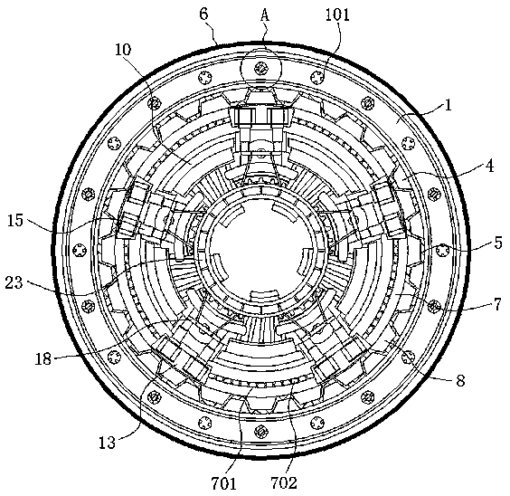
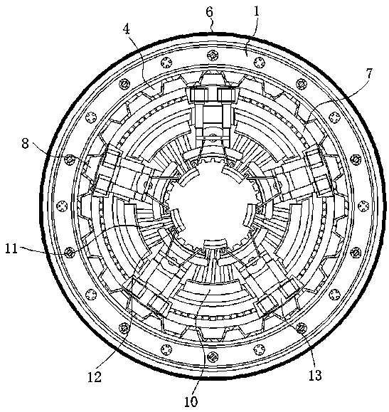
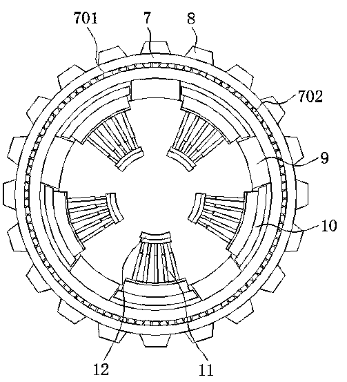
The invention discloses clamp equipment with an adjusting mechanism for bearing machining, and relates to the technical field of clamps for bearing machining. The clamp equipment specifically comprises a clamping ring, a rotary disc, a fixed disc and a bearing ring, wherein clamping teeth are fixed to the inner wall of the clamping ring at equal intervals, the rotary disc is welded to the bottom surface of the clamping ring, the fixed disc is mounted on the inner side of the clamping ring, a bottom plate is welded on the inner side wall of the bottom surface of the fixed disc, and the bearingring is clamped between the end part of a pressing mechanism and the inner side of a hook plate. According to the clamp equipment with the adjusting mechanism for bearing machining, the bearing ring completely does not need to be taken down from the fixed disc and then clamped again when being subjected to machining in multiple procedures through the split structure design of the clamping ring, the rotary disc and the fixed disc, so that secondary clamping of the bearing ring is avoided. In addition, the bearing ring is clamped through the internal and external combined action of the clamp equipment with the adjusting mechanism for bearing machining, so that the bearing ring is stressed inside and outside in a balanced mode, and thus the roundness of the bearing ring can be guaranteed.

Description

technical field [0001] The invention relates to the technical field of fixtures for bearing processing, in particular to a fixture device with an adjustment mechanism for bearing processing. Background technique [0002] Bearing is an important part of contemporary mechanical equipment. Its main function is to support the mechanical rotating body, reduce the friction coefficient during its movement, and ensure its rotation accuracy. Therefore, bearings are rotating bodies, such as shaft parts. One less part, in the processing technology of the bearing, the billet needs to be clamped, which requires the use of special fixtures. [0003] During the processing of large-scale bearings, multiple processing procedures are required. In order to ensure the quality of bearing products, it is necessary to select a suitable bearing fixture to clamp the blank or semi-finished bearing parts. When selecting a fixture, it is necessary to select the bearing material, Bearing processing tec...

Claims


Application Information

Patent Timeline
IPC IPC(8): B23Q3/12
CPCB23Q3/12
Inventor 文婵陈马鑫丘强
Owner DONGGUAN KAILEDI NUMERICAL CONTROL SCI & TECH CO LTD
Learn More