High-automation apparel production line

A production line and ready-made garment technology, applied in the field of garment processing, can solve problems such as complex mechanism settings, stock jams, and shortages

Active Publication Date: 2020-03-31
东莞市质品服饰有限公司
View PDF13 Cites 0 Cited by
  • Summary
  • Abstract
  • Description
  • Claims
  • Application Information

AI Technical Summary

Problems solved by technology

[0002] The existing hanging production line for garment processing is generally composed of a ring-shaped main track, a receiving track, a recovery track, a transmission device and several workstations. The working main track and the main track are connected by a receiving track and a recovery track. The hangers are pushed and conveyed by the push rod on the transmission device. The existing production line keeps the rotating device in running state when it is working, and the energy consumption is high. In addition, once the main track transmission device fails, the entire production line will stop working. At the same time, the main track It is also necessary to set up receiving rails and recovery rails between the station and the workstation, and to install transmission devices, which makes the mechanism settings complicated. In addition, because the transmission devices on the main rail run in a constant speed loop, it is impossible to fully achieve equalization in the front and rear production processes. Under certain circumstances, there will be a phenomenon of blockage or shortage of goods in one of the processes, which will bring inconvenience to production scheduling and require a higher level of overall work efficiency for production line operators

Method used


Image

  • High-automation apparel production line
  • High-automation apparel production line
  • High-automation apparel production line

Examples


Embodiment Construction

[0021] Preferred embodiments of the present invention will be described in detail with reference to the accompanying drawings so that those embodiments can be easily realized by those having ordinary skill in the art to which the present invention pertains. However, the present invention can also be realized in various forms, so the present invention is not limited to the embodiments described hereinafter. In addition, in order to describe the present invention more clearly, parts not connected with the present invention will be omitted from the drawings.

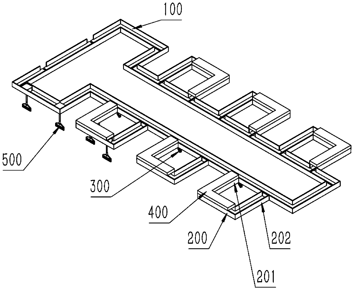
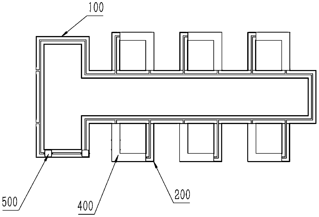
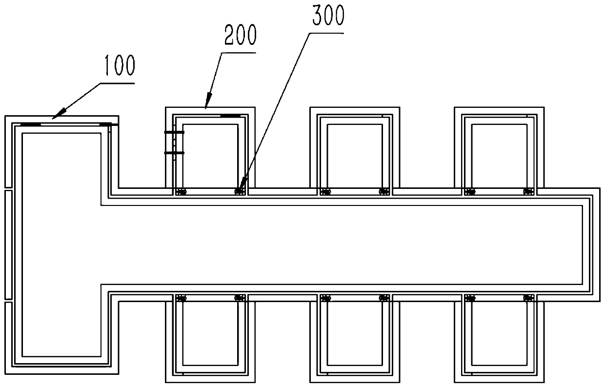
[0022] Such as Figure 1-Figure 8 As shown, a highly automated garment production line includes: a main track 100, a workstation track 200, a track connection device 300, a charging module 400, and a self-propelled clothes hanger 500;

[0023] Such as Figure 1-Figure 4 As shown, the main rail 100 is composed of two convex ring rails with L-shaped cross-sections facing each other to form a U-shaped ring rail with a U-shap...


PUM


Abstract

The invention relates to the technical field of garment processing, in particular to a high-automation apparel production line. The invention discloses the high-automation apparel production line which comprises a main rail, workstation rails, rail connecting devices, charging modules and apparel self-walking hangers. For the high-automation apparel production line disclosed by the invention, thearranged apparel self-walking hangers can flexibly move between the main rail and the corresponding workstation rails; as each apparel self-walking hanger has a power device, even if a certain apparelself-walking hanger has a fault, a system can send out a prompt to manually move the apparel self-walking hanger out of the corresponding workstation rail without affecting production of the whole production line; and meanwhile, when the condition of mismatched working progress between adjacent workstation rails occurs, the system can quickly adjust a moving speed of each apparel self-walking hanger, the station entrance amount of the apparel self-walking hangers and the working progress between the adjacent workstations. For the high-automation apparel production line disclosed by the invention, the charging modules arranged on the workstation rails respectively can charge the corresponding apparel self-walking hanger at the waiting stage thereof, and the production progress is not affected by charging the apparel self-walking hangers by using the residence time.

Description

technical field [0001] The invention relates to the technical field of garment processing, in particular to a highly automated garment production line. Background technique [0002] The existing hanging production line for garment processing is generally composed of a ring-shaped main track, a receiving track, a recovery track, a transmission device and several workstations. The working main track and the main track are connected by a receiving track and a recovery track. The hangers are pushed and conveyed by the push rod on the transmission device. The existing production line keeps the rotating device in running state when it is working, and the energy consumption is high. In addition, once the main track transmission device fails, the entire production line will stop working. At the same time, the main track It is also necessary to set up receiving rails and recovery rails between the station and the workstation, and to install transmission devices, which makes the mecha...

Claims


Application Information

Patent Timeline
Patent Type & Authority Applications(China)
IPC IPC(8): B65G35/06H02J50/00
CPCB65G35/06H02J50/00
Inventor 陈东海
Owner 东莞市质品服饰有限公司
Why Eureka
Try Eureka