
Method for determining position of cooperative system bridge closure segment

A technology for closing sections and systems, applied in bridges, bridge construction, erection/assembly of bridges, etc., can solve time-consuming and labor-intensive problems, achieve strong operability, improve design efficiency, and shorten calculation cycles

Active Publication Date: 2020-03-31
CHINA MAJOR BRIDGE ENERGINEERING
View PDF15 Cites 5 Cited by
  • Summary
  • Abstract
  • Description
  • Claims
  • Application Information

AI Technical Summary

Problems solved by technology

[0007] The purpose of the present invention is to overcome the disadvantages of the calculation method for determining the position of the closing section in the above-mentioned background technology, which requires continuous manual setting of the closing section position and continuous trial calculation, which is obviously time-consuming and labor-intensive, and provides a method for determining the position of the closing section of the collaborative system bridge. method

Method used


Image

  • Method for determining position of cooperative system bridge closure segment
  • Method for determining position of cooperative system bridge closure segment
  • Method for determining position of cooperative system bridge closure segment

Examples


Embodiment

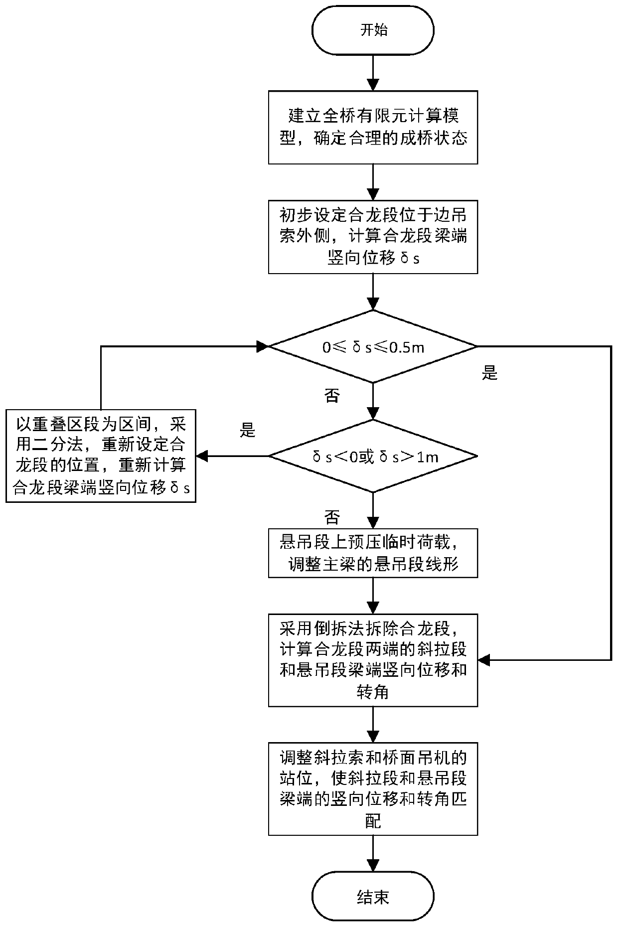
[0038] see figure 1 As shown, the embodiment of the present invention provides a method for determining the position of the bridge closure section of the collaborative system, including the following steps:

[0039] Step 101, see figure 2 and image 3 As shown, the finite element calculation model of the whole bridge is established to determine the reasonable state of the bridge, and n pairs of suspension cables 3 and stay cables 2 are set in the overlapping section of the cable-stayed section 42 and the suspension section 41, and the top of the suspension cable 3 is connected to the The main cable 1 is connected, the top of the stay cable 2 is connected with the main tower 5, the end of the main cable 1 is anchored and connected with the anchorage 7, and the main body of the main cable 1 is connected with the top of the main tower 5 through the main cable saddle. The outer side of 5 is provided with side pier 6, and side pier 6 is used for supporting and connecting side-span...


PUM


Abstract

The invention discloses a method for determining the position of a bridge closure section of a cooperative system, which belongs to the technical field of bridge design and comprises the following steps that a full-bridge finite element calculation model is established, and a reasonable bridge forming state is determined; the closure section is preliminarily set to be located on the outer side ofthe side sling, and based on the unstressed state quantity construction control theory, the beam end vertical displacement delta s of the suspension end of the closure section is obtained through finite element calculation; if delta s is within the set interval range, it is determined that the preliminarily set closure segment position is basically reasonable; and if delta s is not in the set interval range, the overlapped section of the cable-stayed section and the suspension section serves as an interval, the position of the closure section is reset through a dichotomy, the full-bridge finite element calculation model is updated, and the vertical displacement delta s of the beam ends at the two ends of the closure section is recalculated till delta s is within the set interval range. Theoptimal closure position can be calculated, the position of the closure section and the closure scheme can be quickly calculated and determined, the operability is high, the calculation period is shortened, and the design efficiency is improved.

Description

technical field [0001] The invention relates to the technical field of bridge design, in particular to a method for determining the position of a bridge closure section of a collaborative system. Background technique [0002] There are three main forms of cable-supported bridges, cable-stayed bridges, suspension bridges, and cable-stayed-suspension cooperative system bridges. The main girder of a long-span cable-stayed bridge needs to bear the huge axial component force transmitted by the cable. At the same time, in order to ensure the efficiency of the cable-stayed girder, considering the nonlinear sag effect of the cable-stayed cable, the height of the cable tower increases more. Fast, the strength and stability of the main girder and the cable tower become the main factors restricting its spanning ability. [0003] The main stress-bearing components of long-span suspension bridges are anchorages, cable towers, and main cables. The effective bearing efficiency is reduced...

Claims


Application Information

Patent Timeline
Patent Type & Authority Applications(China)
IPC IPC(8): E01D21/00E01D11/00
CPCE01D11/00E01D21/00
Inventor 肖海珠何东升刘俊峰邱远喜潘韬杜方刘扬
Owner CHINA MAJOR BRIDGE ENERGINEERING
Learn More