Terminal group and forming method thereof

A forming method and technology of terminal group, applied in contact parts, circuit/collector parts, welding/welding connection, etc., can solve the problems affecting the overall appearance of the terminal group's electrical conductivity, serious burns, burns, etc.

Active Publication Date: 2021-02-26
DEYI PRECISION ELECTRONIC IND CO LTD PANYU
View PDF10 Cites 0 Cited by
  • Summary
  • Abstract
  • Description
  • Claims
  • Application Information

AI Technical Summary

Problems solved by technology

[0004] However, since the above operation needs to be irradiated on the board surface of the uppermost conductive terminal for a long time, it is easy to cause the board surface of the uppermost conductive terminal to be burned due to overheating, especially in the case where the number of the conductive terminals is larger. Under normal circumstances, the degree of burn is more serious, which affects the electrical conductivity and overall appearance of the terminal group

Method used


Image

  • Terminal group and forming method thereof
  • Terminal group and forming method thereof
  • Terminal group and forming method thereof

Examples


Embodiment Construction

[0047] In order to facilitate a better understanding of the purpose, structure, features, and effects of the present invention, the present invention will now be further described in conjunction with the accompanying drawings and specific embodiments.

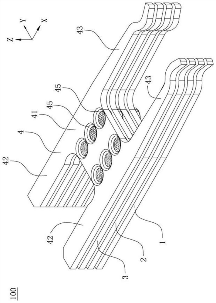
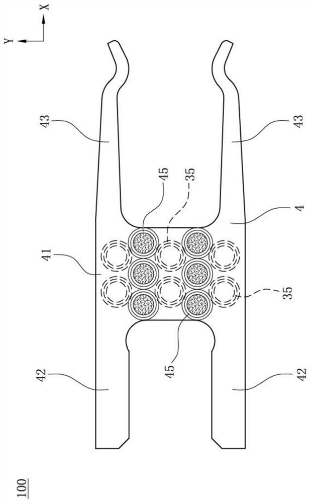
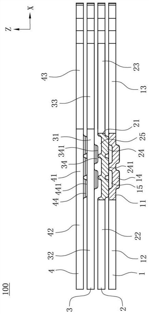
[0048] The present invention defines the X-axis direction as the front-rear direction, the Y-axis direction as the left-right direction, and the Z-axis direction as the up-down direction.

[0049] Such as figure 1 , Figure 4 and Figure 5 Shown is a terminal set 100 of the present invention, which electrically connects a lead piece 200 to a connecting piece 300 for transmitting large current. In this embodiment, the lead member 200 is a copper plate and is electrically connected to the rear end of the terminal group 100, and the rear end of the lead member 200 is also electrically connected to a cable (not shown in the figure). ), the docking member 300 is an electronic card and is electrically connected to the front end of...


PUM


Abstract

The invention discloses a terminal group and a forming method thereof. The terminal group comprises: a lower terminal, which has a lower body part and a lower contact arm extending forward from the lower body part; a first upper terminal, which has a first upper body part 1. A first upper convex part protrudes downward from the first upper main body, and a first upper contact arm extends forward from the first upper main body. The first upper contact arm and the lower contact arm are spaced up and down, and each second An upper convex part has a first upper welding plane that abuts against the top surface of the lower main part downwards and is laser welded with the top surface of the lower main part; a second upper terminal has a second upper main part, The second upper convex part is protruded downward, and the second upper contact arm extends forward from the second upper main body part. The second upper contact arm is spaced apart from the first upper contact arm. The upper convex parts are arranged vertically staggered, and each second upper convex part has a second upper welding plane abutting against the top surface of the first upper body part and laser welding with the top surface of the first upper body part.

Description

【Technical field】 [0001] The invention relates to a terminal group and its forming method, in particular to a terminal group for transmitting large current and its forming method. 【Background technique】 [0002] A terminal set in the prior art is used to electrically connect a pair of joints to transmit large currents. The terminal set includes a plurality of conductive terminals in the shape of a plate, and each conductive terminal has a contact arm for contacting the butt joint. A plurality of conductive terminals are stacked together in a vertical direction, and the board surfaces of two vertically adjacent conductive terminals are in contact with each other. In order to be suitable for transmitting large currents, the number of the conductive terminals is generally three or more. [0003] When the terminal group is formed, a plurality of conductive terminals are first stacked together in the vertical direction, so that the board surfaces of the two adjacent conductive t...

Claims


Application Information

Patent Timeline
Patent Type & Authority Patents(China)
IPC IPC(8): H01R13/02H01R4/02H01R43/16H01R43/02
CPCH01R4/029H01R13/02H01R43/0221H01R43/0263H01R43/16
Inventor 金左锋
Owner DEYI PRECISION ELECTRONIC IND CO LTD PANYU
Why Eureka
Try Eureka