Current balance control circuit and method for matrix LED lamp

A LED lamp and current balance technology, applied in the direction of electrical components, can solve the problems of current balance out of control and low cost, and achieve the effect of fewer components, simple and reliable process, and easy promotion

Inactive Publication Date: 2020-03-31
VATTI CORP LTD
View PDF5 Cites 0 Cited by
  • Summary
  • Abstract
  • Description
  • Claims
  • Application Information

AI Technical Summary

Problems solved by technology

[0004] In order to solve the above problems, the present invention provides a current balance control circuit for matrix LED lamps. By connecting the matrix resistors in series, the forward voltage drop error of the matrix LED lamp itself can be solved, thereby solving the problem of out-of-control current balance ; and the circuit can be realized only by adding resistance, and the cost is low

Method used


Image

  • Current balance control circuit and method for matrix LED lamp
  • Current balance control circuit and method for matrix LED lamp
  • Current balance control circuit and method for matrix LED lamp

Examples


Embodiment 1

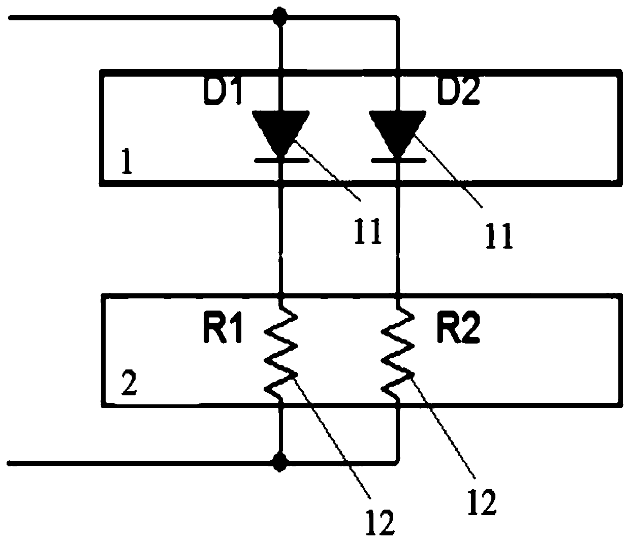
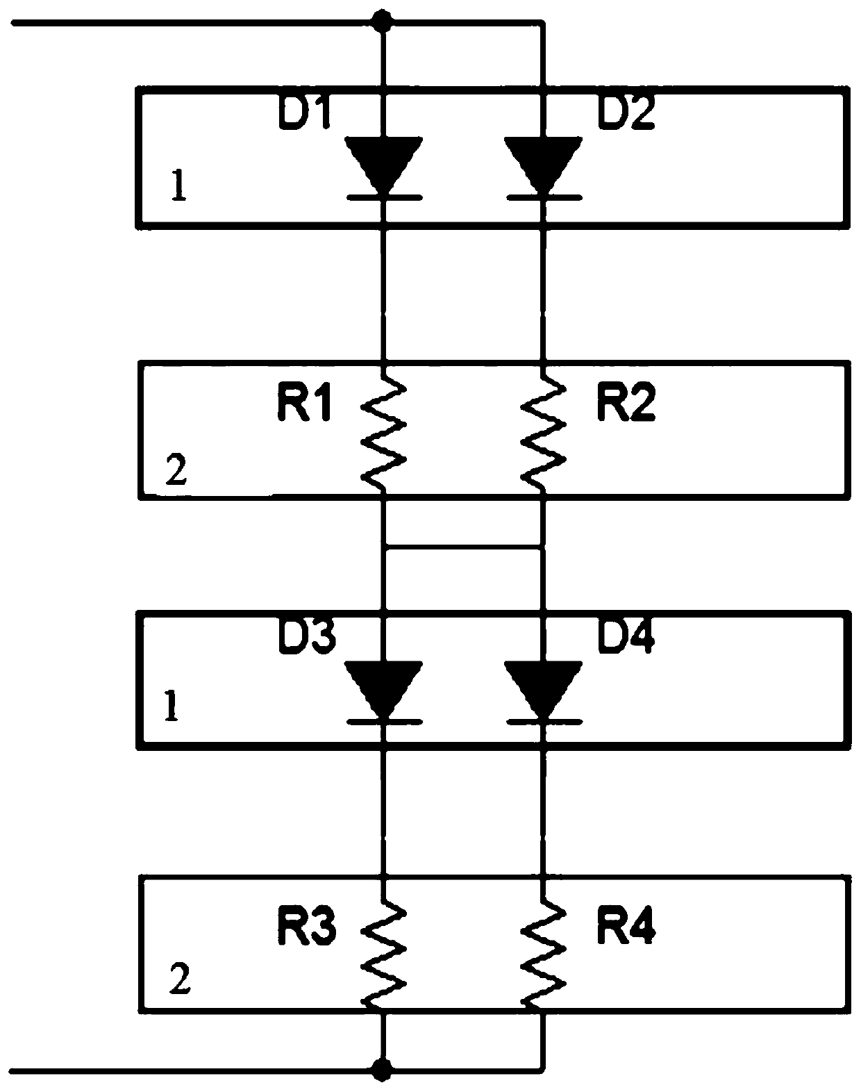
[0033] Embodiment 1 of the present invention provides a current balance control circuit for a matrix LED lamp, the circuit includes at least one matrix LED lamp 1 and a matrix resistor 2, the number of the matrix LED lamp 1 and the matrix resistor 2 are the same, and the The matrix resistor 2 and the matrix LED lamp 1 are connected in series to control the current balance of the matrix LED lamp 1 by adjusting the voltage drop difference of the LED lamp;

[0034] In this way, by adopting the above-mentioned structure, by connecting the matrix resistor 2 in series with the matrix LED lamp 1, the error of the forward voltage drop of the matrix LED lamp 1 itself is solved, thereby solving the problem of out-of-control current balance.

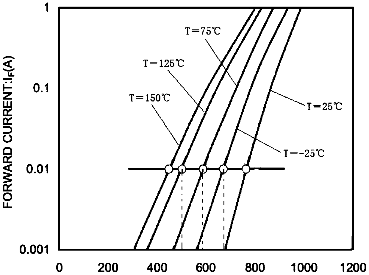
[0035] Each of the matrix LED lamps 1 includes at least two parallel LED lamps 11, and the two LED lamps 11 are located at the same ambient temperature for avoiding different temperatures from affecting the accuracy of the current;

[0036] The amb...

Embodiment 2

[0054] Embodiment 2 of the present invention provides a current balance control method for matrix LED lamps, which uses the current balance control circuit for matrix LED lamps described in Embodiment 1. The method is specifically:

[0055] S1, calculate the unbalanced current of the LED lamp;

[0056] S2, controlling the unbalanced current through the parameters affecting the unbalanced current of the LED lamp in S1.

[0057] The calculation of the unbalanced current of the LED lamp in the S1 is specifically:

[0058] Calculate the unbalanced current of the LED lamp by the following formula;

[0059] ΔI=ΔV / R

[0060] In the above formula, ΔI is the unbalanced current of the LED lamp 11 , ΔV is the voltage drop difference between adjacent LED lamps 11 , and R is the resistance value of the resistor 21 .

[0061] In the S2, the unbalanced current is controlled through the parameters affecting the unbalanced current of the LED lamp in the S1, specifically:

[0062] ΔV is a f...


PUM


Abstract

The invention discloses a current balance control circuit for a matrix LED lamp. The circuit comprises at least one matrix LED lamp and matrix resistors, the number of the matrix LED lamps is the sameas that of the matrix resistors, and the matrix resistors and the matrix LED lamps are connected in series and used for controlling current balance of the matrix LED lamps by adjusting the voltage drop difference of the LED lamps. The invention further discloses a current balance control method for the matrix LED lamp. According to the invention, a constant-current chip in the prior art is abandoned, and the complexity and hardware cost in the design process are reduced; matrix resistors with certain resistance and precision are connected in series with the matrix LED lamps, so that the brightness, temperature and current precision of the LED lamps are controlled; control over the current balance can be achieved through a simple resistor, the number of components is small, the process issimple and reliable, and popularization is easy.

Description

technical field [0001] The invention belongs to the technical field of LED lamp current balance control, and in particular relates to a current balance control circuit and a control method for matrix LED lamps. Background technique [0002] The main method of the matrix LED current balance control circuit on the market is generally: current control based on a dedicated LED constant current chip. [0003] The above method is relatively simple in form, and only needs a constant current chip; but the dedicated chip is expensive, and in order to meet the functions of the chip, more peripheral circuits and unit machines are required, which leads to high hardware costs. , There are too many detection ports, and the LED current is greatly affected by temperature. Contents of the invention [0004] In order to solve the above problems, the present invention provides a current balance control circuit for matrix LED lamps. By connecting the matrix resistors in series, the forward v...

Claims


Application Information

Patent Timeline
Patent Type & Authority Applications(China)
IPC IPC(8): H05B45/30
Inventor 李耀聪潘叶江
Owner VATTI CORP LTD
Why Eureka
Try Eureka