
A real-time intelligent detection device for civil engineering buildings

An intelligent detection and civil engineering technology, which is applied in the direction of mechanical equipment, supporting machines, machine platforms/supports, etc., can solve the problems of rough position adjustment, detection equipment cannot be aimed accurately, etc., and achieve the effect of ensuring measurement accuracy

Active Publication Date: 2021-06-08
苏州东大工程咨询管理有限公司
View PDF5 Cites 0 Cited by
  • Summary
  • Abstract
  • Description
  • Claims
  • Application Information

AI Technical Summary

Problems solved by technology

[0002] In the civil engineering construction in the prior art, real-time intelligent detection equipment, such as laser signal detection equipment, is used to fix the equipment on the support frame, and some vertical poles on the support frame are nailed into the ground, so as to ensure the positioning of the detection equipment without Affected by the external environment, such as the impact of wind blowing, if the detection equipment cannot be aimed accurately after the support frame is positioned, because the laser emitted by the instrument needs to be attached to the wall and the laser is irradiated upwards, how to make the laser emitted by the instrument The laser is close to the outer wall of the building to monitor the shape of the building, which requires fine position adjustment of the laser emission source. The support frame is only convenient for rough position adjustment. For this reason, we provide a real-time intelligent detection equipment for civil engineering buildings.

Method used


Image

  • A real-time intelligent detection device for civil engineering buildings
  • A real-time intelligent detection device for civil engineering buildings
  • A real-time intelligent detection device for civil engineering buildings

Examples


Embodiment Construction

[0017] The following will clearly and completely describe the technical solutions in the embodiments of the present invention with reference to the accompanying drawings in the embodiments of the present invention. Obviously, the described embodiments are only some, not all, embodiments of the present invention. Based on the technical solutions in the present invention, all other embodiments obtained by persons of ordinary skill in the art without making creative efforts belong to the protection scope of the present invention.

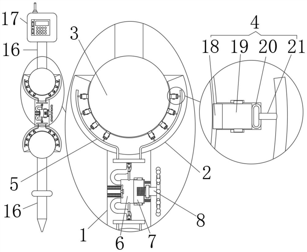
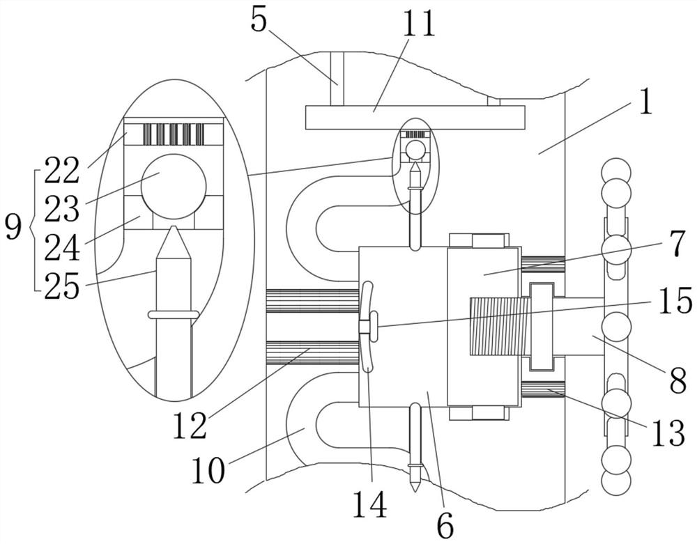
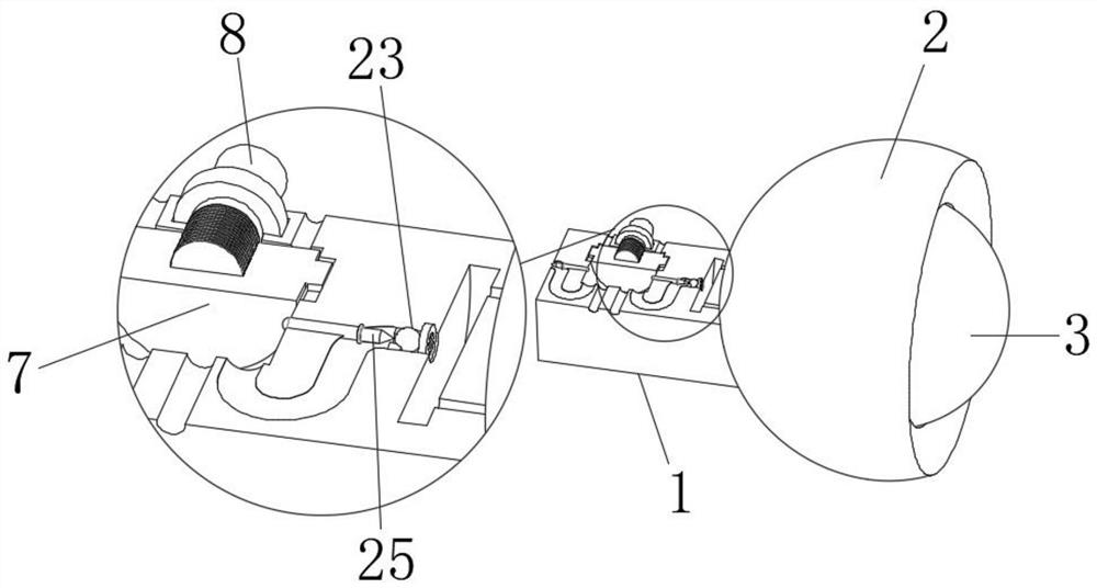
[0018] see Figure 1 to Figure 3 , the present invention provides a technical solution: a real-time intelligent detection device for civil engineering construction, including a cuboid control rod 1, and a spherical shell-shaped hinged shell 2 is fixedly connected to both ends of the control rod 1, and the hinged shell 2 A hinged ball 3 is fitted in the inner cavity of the hinged shell 2, and a number of evenly distributed clamping devices 4 are arrange...


PUM


Abstract

The invention relates to the technical field of building surveying, in particular to a real-time intelligent detection device for civil engineering buildings, which includes a cuboid-shaped control rod, each of which ends of the control rod is fixedly connected with a spherical shell-shaped hinged shell, and the inner cavity of the hinged shell There are hinged balls in the middle fit, and several evenly distributed locking devices are arranged on the hinged shell shell, which are located on one side of the hinged balls. The upper ring of the hinged shell is provided with a number of uniformly distributed collecting and distributing lumens. One end of the locking device and the collecting and distributing pipe Cavities are connected, and a columnar cavity is opened in the middle of the control rod. The structural design of the present invention realizes the flexible rotation between the hinge shell and the hinge ball, and realizes several clamping devices firmly clamping the hinge ball through high pressure, and then realizes the stable shape of the present invention. This ensures that after the outer rod is nailed into the ground, the detection device will not be affected by the external environment, and the detection device remains stable to ensure the measurement accuracy of the detection device.

Description

technical field [0001] The invention relates to the technical field of building measurement, in particular to a real-time intelligent detection device for civil engineering buildings. Background technique [0002] In the civil engineering construction in the prior art, real-time intelligent detection equipment, such as laser signal detection equipment, is used to fix the equipment on the support frame, and some vertical poles on the support frame are nailed into the ground, so as to ensure the positioning of the detection equipment without Affected by the external environment, such as the impact of wind blowing, if the detection equipment cannot be aimed accurately after the support frame is positioned, because the laser emitted by the instrument needs to be attached to the wall and the laser is irradiated upwards, how to make the laser emitted by the instrument The laser is close to the outer wall of the building to monitor the shape of the building, which requires fine pos...

Claims


Application Information

Patent Timeline
Patent Type & Authority Patents(China)
IPC IPC(8): F16M11/22F16M11/14F16M11/16
CPCF16M11/14F16M11/16F16M11/2078F16M11/22F16M2200/022
Inventor 黄杨吕家琦
Owner 苏州东大工程咨询管理有限公司
Learn More