
Hub end face deformation detection method and device

A detection method and wheel hub technology, applied in the field of vehicle detection, can solve problems such as slow test speed, difficulty in meeting production line production requirements, and deformation of the end face of automobile wheel hubs.

Active Publication Date: 2020-04-03
SUZHOU YIMEIDE TECH CO LTD
View PDF8 Cites 4 Cited by
  • Summary
  • Abstract
  • Description
  • Claims
  • Application Information

AI Technical Summary

Problems solved by technology

At present, most of the methods used to measure automobile hubs are direct measurement with contact dial indicators. This detection method has slow test speed and low test accuracy, and it is difficult to meet the production needs of the production line.
At present, laser ranging is also used to detect the deformation of the end face of the automobile wheel hub, but since the laser ranging is the distance measured from a certain point on the end face of the automobile wheel hub, there may be tiny protrusions or recessed holes at a certain point on the end face of the automobile wheel hub, etc. But it did not really cause the deformation of the end face of the car hub
Therefore, these points cannot accurately and truly reflect the deformation at a certain point on the end face of the automobile hub. It is only because of some special reasons that some points are raised or recessed relative to the surrounding end face. If the distance obtained directly includes the points in the above cases To finally calculate the deformation of the end face of the automobile hub, the reliability and accuracy of the obtained deformation may be low

Method used


Image

  • Hub end face deformation detection method and device
  • Hub end face deformation detection method and device
  • Hub end face deformation detection method and device

Examples


Embodiment Construction

[0048] The details of the present invention can be understood more clearly with reference to the accompanying drawings and the description of specific embodiments of the present invention. However, the specific embodiments of the present invention described here are only for the purpose of explaining the present invention, and should not be construed as limiting the present invention in any way. Under the teaching of the present invention, the skilled person can conceive any possible modification based on the present invention, and these should be regarded as belonging to the scope of the present invention. It should be noted that when an element is referred to as being “disposed on” another element, it may be directly on the other element or there may also be an intervening element. When an element is referred to as being "connected to" another element, it can be directly connected to the other element or intervening elements may also be present. The terms "mounted", "connec...


PUM


Abstract

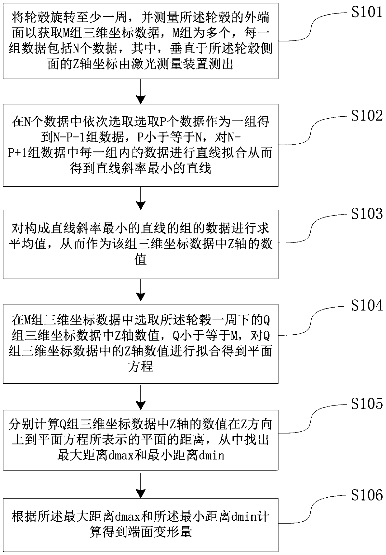
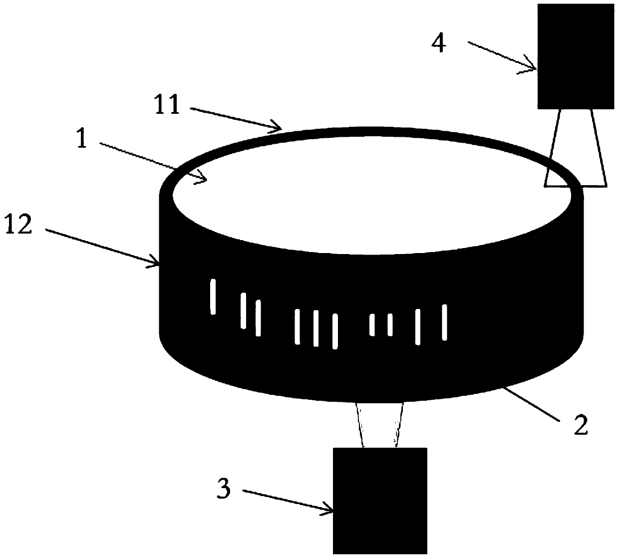
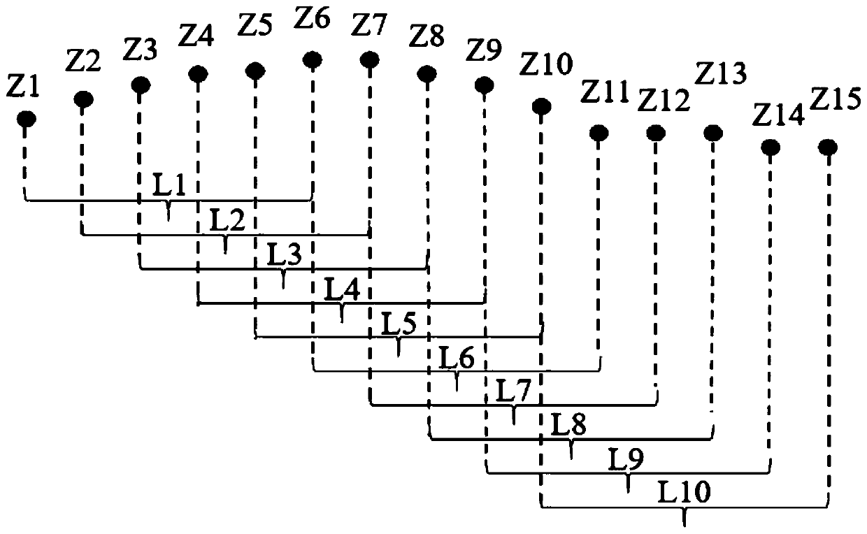
The invention discloses a hub end face deformation detection method and a hub end face deformation detection device. The invention relates to the technical field of vehicle detection. The method comprises the steps that a hub is rotated by at least one circle, the outer end face of the hub is measured to obtain M sets of three-dimensional coordinate data, the number of the M sets is multiple, eachset of data comprises N parts of data, and Z-axis coordinates perpendicular to the side face of the hub are measured by a laser measuring device; p parts of data are sequentially selected from the Nparts of data to serve as a set to obtain N-P + 1 sets of data, P is smaller than or equal to N, and straight line fitting is conducted on the data in each set in the N-P + 1 sets of data to obtain astraight line with the minimum straight line slope; averaging the data constituting the group of straight lines having the smallest straight line slope as the numerical value of the Z axis in the group of three-dimensional coordinate data; equal. According to the invention, the accurate hub end face deformation with high reliability can be obtained through a large amount of data of the hub end face measured by laser.

Description

technical field [0001] The invention relates to the technical field of vehicle detection, in particular to a method and a device for detecting deformation of a wheel hub end face. Background technique [0002] The automobile hub is an important part of the wheel, and its safety performance and mechanical characteristics have an important impact on the safe operation of the automobile. Therefore, it is of great significance to detect the deformation of the end surface of the automobile hub. At present, most of the methods used to measure automobile hubs are direct measurement with contact dial indicators. This detection method has slow test speed and low test accuracy, and it is difficult to meet the production needs of the production line. At present, laser ranging is also used to detect the deformation of the end face of the automobile wheel hub, but since the laser ranging is the distance measured from a certain point on the end face of the automobile wheel hub, there may ...

Claims


Application Information

Patent Timeline
IPC IPC(8): G01B11/16
CPCG01B11/16
Inventor 王永兴倪志庭
Owner SUZHOU YIMEIDE TECH CO LTD
Learn More