digital micromirror array dmd beam expander

A digital micromirror array and micromirror technology, applied in the field of digital micromirror array DMD, can solve problems such as light energy loss, and achieve the effect of expanding the divergence angle

Active Publication Date: 2022-03-04
BEIJING SIMULATION CENT
View PDF11 Cites 0 Cited by
  • Summary
  • Abstract
  • Description
  • Claims
  • Application Information

AI Technical Summary

Problems solved by technology

[0003] like image 3 As shown, when the divergence angle of the incident beam exceeds 24°, the optical path of the reflected beam and the optical path of the incident beam will partially overlap. According to the principle of reversible optical paths, the outgoing light in the overlapping area will return to the lighting source along the incident optical path, resulting in loss of light energy.

Method used


Image

  • digital micromirror array dmd beam expander
  • digital micromirror array dmd beam expander
  • digital micromirror array dmd beam expander

Examples


Embodiment Construction

[0014] In order to make the purpose, technical solutions and advantages of the embodiments of the present invention clearer, the technical solutions of the present invention will be clearly and completely described below in conjunction with the accompanying drawings. The described embodiments are part of the embodiments of the present invention, not all of them. example.

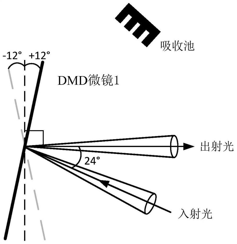
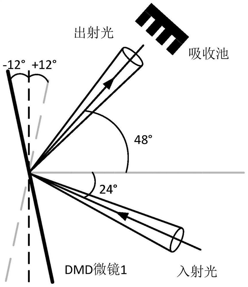
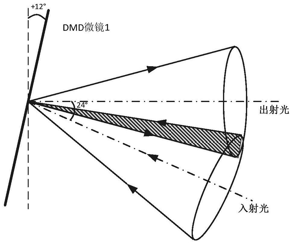
[0015] Figure 4 It is a schematic diagram of a digital micromirror array DMD beam expander device according to an embodiment of the present invention, as Figure 4 As shown, a digital micromirror array DMD beam expander includes: DMD micromirror 10, polarizer 20, analyzer 30 and λ / 4 wave plate 40; incident light is modulated into the first line through polarizer 20 Polarized light, the first linearly polarized light is reflected to the DMD micromirror 10 by the analyzer 30; 10 The static normal is at an angle of 24°; the λ / 4 wave plate 40 is located between the analyzer 30 and the DMD micromirror 10, and ...


PUM


Abstract

The invention discloses a digital micromirror array DMD beam expander, comprising: a DMD micromirror, a polarizer, an analyzer and a λ / 4 wave plate; the incident light is modulated into the first linearly polarized light by the polarizer, and the second A line of polarized light is reflected by the analyzer to the DMD micromirror; adjust the position of the analyzer and / or the angle of the incident light so that the optical axis of the reflected light of the analyzer and the static normal of the DMD micromirror are clamped at 24° angle; the λ / 4 wave plate is located between the analyzer and the DMD micromirror, and the first linearly polarized light reflected by the analyzer becomes circularly polarized light after passing through the λ / 4 wave plate; when the DMD micromirror is in the open state, the circularly polarized light The polarized light is reflected by the DMD micromirror and then passes through the λ / 4 wave plate to become the second linearly polarized light perpendicular to the polarization state of the first linearly polarized light; The normal line is at an angle of 48°; when the DMD micromirror is on and off, the outgoing light paths do not overlap. The technical scheme of the invention adds a polarizer, an analyzer and a λ / 4 wave plate on the basis of the DMD micromirror, and realizes the purpose of expanding the beam divergence angle.

Description

technical field [0001] The invention relates to the field of digital micromirror array DMD, in particular to a digital micromirror array DMD beam expander. Background technique [0002] Digital Micro-mirror Device (DMD) is a commonly used spatial light modulation device developed by Texas Instruments. In the prior art, the DMD micromirror realizes optical path control according to the deflection of the micromirror, and realizes gray scale modulation by time accumulation. At present, the deflection angle of the DMD micromirror is set to two states of +12° and -12°. The conventional use method of the DMD micromirror is as follows: figure 1 and figure 2 As shown, the incident light source and the DMD micromirror are incident at an angle of 24°. When the DMD micromirror is at +12°, the state is defined as the on state, such as figure 1 As shown at this time, the outgoing light exits along the normal direction of the DMD micromirror, and the angle between the incident light a...

Claims


Application Information

Patent Timeline
Patent Type & Authority Patents(China)
IPC IPC(8): G02B26/08G02B26/10G02B27/28
CPCG02B26/0816G02B26/10G02B27/286
Inventor 张兴
Owner BEIJING SIMULATION CENT
Why Eureka
Try Eureka