
Automatic transfer switch, dual power automatic transfer switch and manufacturing method thereof

A technology of automatic transfer switch and manufacturing method, applied in the direction of electric switch, emergency power supply arrangement, circuit, etc., can solve the problems of slow transfer time, large product volume, long transfer time, etc., achieve short development cycle, small size, reduce transmission link effect

Active Publication Date: 2022-05-27
SCHNEIDER ELECTRIC IND SAS
View PDF0 Cites 0 Cited by
  • Summary
  • Abstract
  • Description
  • Claims
  • Application Information

AI Technical Summary

Problems solved by technology

However, it has the disadvantages of large product volume, and the switching mechanism has many limitations due to the need to drive the original switch mechanism, such as long driving stroke and slow switching time.
[0003] A kind of primitive type automatic changeover switch of the prior art, because it has done remodeling to the mechanism of original executive switch, makes its required stroke shorter than original switch, so the power of motor is smaller than derivative type ( Under the same conversion time requirements), but it still has the disadvantages of large volume and long conversion time

Method used


Image

  • Automatic transfer switch, dual power automatic transfer switch and manufacturing method thereof
  • Automatic transfer switch, dual power automatic transfer switch and manufacturing method thereof
  • Automatic transfer switch, dual power automatic transfer switch and manufacturing method thereof

Examples


no. 1 approach

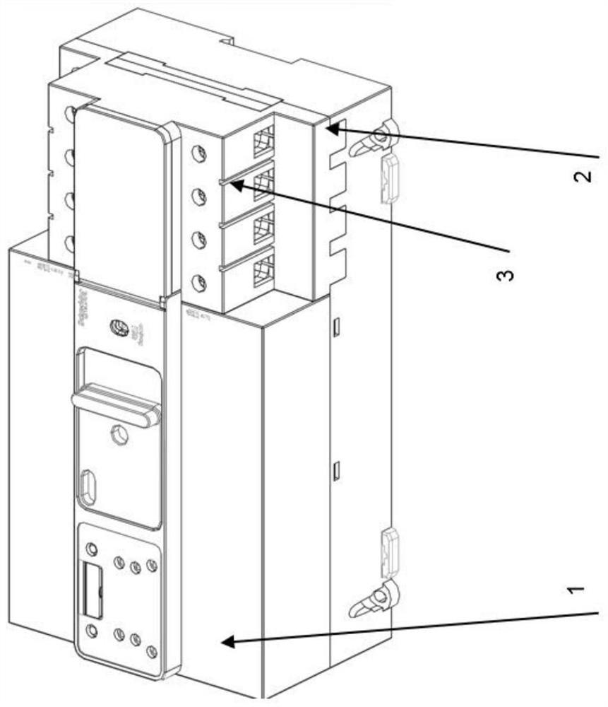
[0070] Figure 2 be Figure 1 Schematic diagram of the first embodiment of the automatic transfer switch shown in; Figure 3 be Figure 2 Exemplary physical diagram of the first embodiment of the automatic transfer switch shown in; Figure 4 be Figure 3 View of the shell removal of the shell of the exemplary physical drawing of the first embodiment of the automatic transfer switch shown in the automatic transfer switch; Figure 5 be Figure 4A local magnified view of the exemplary physical drawing of the shell removal of the first embodiment of the automatic transfer switch shown in the automatic transfer switch.

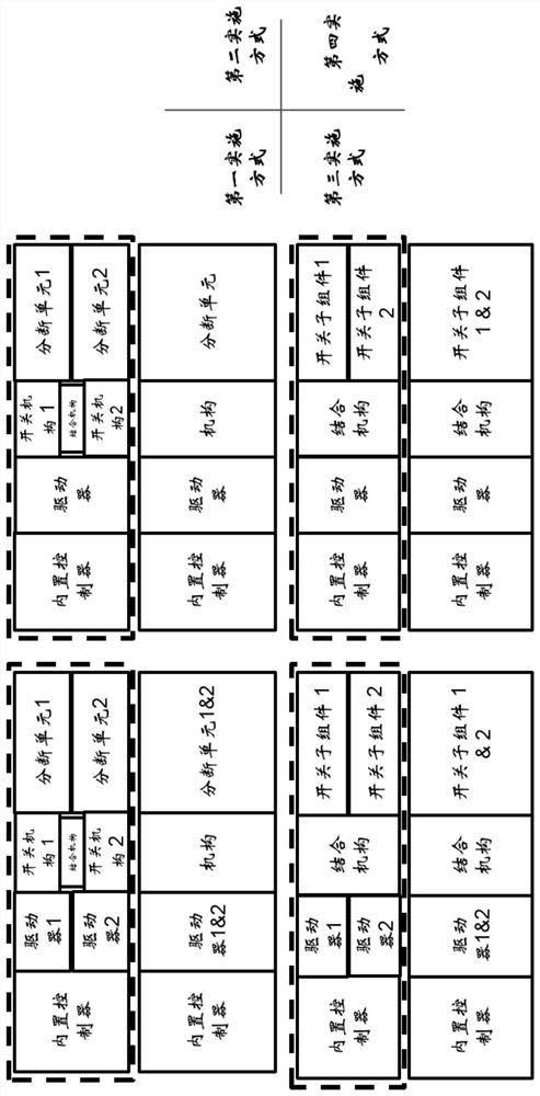
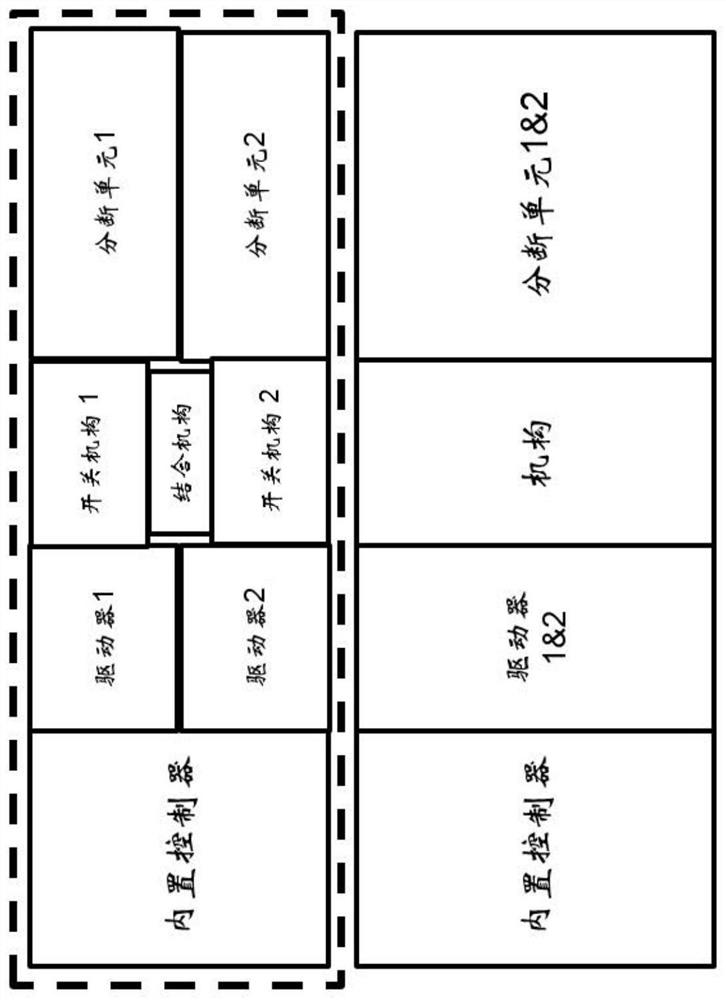
[0071] from Figure 2 The automatic transfer switch according to the present invention is composed of a first switch module and a second switch module superimposed, the first switch module comprises a first built-in controller, a first driver, a first switching mechanism and a first breaking unit, a second switching module comprising a second built-in controller, a second driv...

no. 2 approach

[0074]Figure 6 Yes, accordingly Figure 1 Schematic diagram of the second embodiment of the automatic transfer switch shown in; Figure 7 Yes, accordingly Figure 6 An exemplary physical view of the second embodiment of the automatic transfer switch shown in the physical diagram. Reference Figure 6 and Figure 7 It can be seen that, according to a second embodiment of the automatic transfer switch of the present invention, the first breaking unit 2 and the second breaking unit 3 are superimposed, the first switching mechanism 6 and the second switching mechanism 7 are superimposed, and the first embodiment is different, the superimposed first switching mechanism 6 and the second switching mechanism 7 are disposed between the superimposed first breaking unit 2 and the second breaking unit 3, Further, the corresponding first driver 4 and the second switch mechanism 7 of the first switch mechanism 4 and the second driver 5 are set at the same level as the first switch mechanism 6 and the...

no. 3 approach

[0077] Figure 8 Yes, accordingly Figure 1 Schematic diagram of the third embodiment of the automatic transfer switch shown in; Figure 9 Yes, accordingly Figure 8 An exemplary physical diagram of the third embodiment of the automatic transfer switch shown in. The third embodiment is similar to the first embodiment described above. from Figure 8 and Figure 9It can be seen that the first breaking unit 2 and the second breaking unit 3 are superimposed, the superimposed first switching mechanism and the second switching mechanism and the combined mechanism arranged between the first switching mechanism and the second switching mechanism together constitute an automatic transfer switch mechanism according to the present invention 6,7,9. The difference is that, in this third embodiment of the automatic transfer switch according to the present invention, the first driver and the second driver are replaced by a driver. The mechanism 6,7,9 of the automatic transfer switch and the driver ar...


PUM


Abstract

The invention discloses an automatic transfer switch, comprising: a first switch module and a second switch module, respectively including first and second breaking units, first and second drivers, and first and second switching mechanisms, the first or second The second driver urges the first or second breaking unit to connect and disconnect the load with the first power supply or with the second power supply via the first or second switch mechanism; wherein, the first breaking unit and the second power supply The two breaking units are stacked along the thickness direction of the automatic transfer switch, and also include a coupling mechanism, which is arranged on the side of the stacked first breaking unit and the second breaking unit, for connecting the first switching mechanism and the second switching mechanism to each other connection, so that before one of the first or second breaking unit connects the load to the corresponding power source, the other of the first or second breaking unit disconnects the load from another power source. The invention inherits the original performance advantages of the parts of the switch module, and also has the advantages of small size, compact structure, high reliability, short development cycle and the like.

Description

Technical field [0001] The present invention relates to an automatic transfer switch, more particularly, to an automatic transfer switch using an existing switch module modification configuration. The present invention further relates to a dual power automatic transfer switch comprising an automatic turn-on switch and a manufacturing method thereof. Background [0002] The derived automatic transfer switch is composed of two isolating switches and a set of switching mechanisms, which are loved by manufacturers because of the fewer parts of the newly designed parts and the implementation switch is a mature product, so it has the advantages of short project cycle and low product cost. However, it has a large product volume, and the conversion mechanism is more restricted due to the reasons of driving the original switch mechanism, such as long driving stroke and slow conversion time. [0003] A native type of automatic transfer switch of the prior art, because it has reshaped the m...

Claims


Application Information

Patent Timeline
Patent Type & Authority Patents(China)
IPC IPC(8): H01H3/00H01H9/26H02J9/06
CPCH01H3/00H01H9/26H02J9/06
Inventor 刘振忠曾晓菁
Owner SCHNEIDER ELECTRIC IND SAS
Learn More