dropout fuse

A technology for drop-out fuses and fuse tubes, which is applied to emergency protection devices, circuits, electrical components, etc., and can solve problems such as increasing the difficulty of closing the operating lever and preventing the fuse tube from falling

Active Publication Date: 2021-12-17
TAMPA FUJIAN ELECTRIC
View PDF0 Cites 0 Cited by
  • Summary
  • Abstract
  • Description
  • Claims
  • Application Information

AI Technical Summary

Problems solved by technology

[0004] However, in some windy areas, such as wind power plants, the fuse body may be blown off by the wind without failure due to the wind force. Additional constraints are added to the fuse body, which not only increases the difficulty of closing the operating lever, but also may prevent the fuse body from falling in the event of a real failure. Fuses that quickly cut off the circuit due to the rapid drop of the fuse tube become necessary

Method used


Image

  • dropout fuse
  • dropout fuse
  • dropout fuse

Examples


Embodiment Construction

[0027] The present invention will be further described below in conjunction with accompanying drawing:

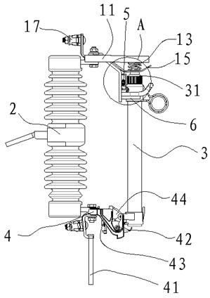
[0028] Such as Figure 1-7 As shown, the present embodiment provides a drop-out fuse, which includes an insulator 2, a lower electrode 4, a mounting column 56, a side pushing device 5 and a clamping device 6, and the lower electrode 4 is fixed with an electric test grounding pull ring 41 and is tested. The electric grounding pull ring 41 is located outside the drop path of the fuse tube, so that when the fuse is blown and the fuse tube falls down, it will not touch the electric test ground pull ring 41, which greatly prolongs the use of the electric test ground pull ring 41 The upper electrode and the lower electrode 4 are arranged at both ends of the insulator 2 and insulated by the insulator 2 .

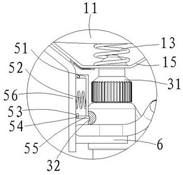
[0029] In this embodiment, the upper electrode includes an upper electrode connection plate 17, a static contact piece 15, a main pressure spring 13 and a rain shield 11, the u...


PUM


Abstract

The invention relates to a drop-out fuse, which includes an insulator, a fuse tube, an upper electrode, a lower electrode, a mounting column, a side pushing device and a clamping device, the upper electrode and the lower electrode are arranged at two ends of the insulator, and the upper electrode includes an upper electrode Connecting plate, static contact piece, main pressure spring and rain shield, the mounting column is fixed on the upper electrode connecting plate, the fuse tube is provided with a first step, a second step and a fixed protrusion; the side pusher is installed on the mounting column The clamping device is fixed on the mounting column and slides along the fuse tube. The clamping device has two states of closing and opening by cooperating with the first step and the second step. The clamping device When it is in the closed state, it buckles the fixed protrusion and when it is in the open state, it is out of contact with the fixed protrusion. It has the function of windproof and at the same time it is convenient for the fuse tube to drop quickly and cut off the circuit quickly.

Description

technical field [0001] The invention relates to the technical field of fuses, in particular to a dropout fuse. Background technique [0002] The drop-out fuse is composed of the following parts, including an insulator and a fuse tube. The upper and lower electrodes of the insulator are respectively fixed with an upper electrode connection plate and a lower electrode connection plate. The upper electrode connection plate is fixed with a static contact piece and a rain cover in turn. , a main compression spring is set between the static contact piece and the rain shield, a bracket is fixed on the lower electrode connecting plate, a trunnion matched with the bracket and a tripper with a small spring are arranged, and a fuse is arranged in the fuse body. One end of the fuse is pressed tightly by the pressure release cap provided on the upper end of the fuse body, and the opposite end of the fuse is fixed on the lower electrode connection plate through a tripper, and the fuse is ...

Claims


Application Information

Patent Timeline
Patent Type & Authority Patents(China)
IPC IPC(8): H01H85/54H01H85/20H01H85/22
CPCH01H85/54H01H85/20H01H85/22Y02E60/10
Inventor 郭晨章婧陈群郭文川王漳泉洪伟聪陈立
Owner TAMPA FUJIAN ELECTRIC
Why Eureka
Try Eureka