Exposure apparatus

An exposure device and technology for irradiating light, which can be applied to exposure devices for photo-engraving processes, exposure equipment for microlithography, optics, etc., and can solve problems such as prolonged exposure processing time.

Active Publication Date: 2010-09-22
USHIO DENKI KK
View PDF6 Cites 2 Cited by
  • Summary
  • Abstract
  • Description
  • Claims
  • Application Information

AI Technical Summary

Problems solved by technology

[0028] Thus, with the above Figure 10 Compared with the conveying sequence of the workpiece W shown in , the sequence of moving the slider 32 toward the pre-alignment table 50 and returning to the exposure position is increased, so the exposure processing time (tact time) is correspondingly longer.

Method used


Image

  • Exposure apparatus
  • Exposure apparatus
  • Exposure apparatus

Examples


Embodiment Construction

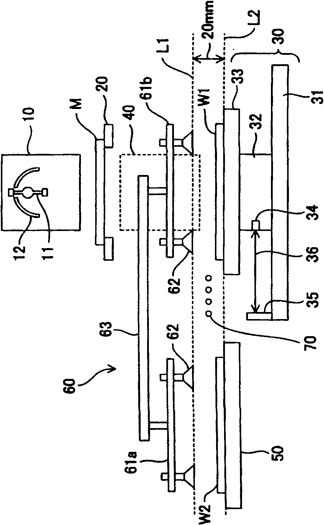
[0054] figure 1 It is a figure which shows the schematic structure of the exposure apparatus of the 1st Example of this invention. Among them, about the Figure 10 The same configuration is marked with the same symbol.

[0055] The exposure apparatus of the present invention includes: a light irradiation unit 10; a mask M on which a pattern transferred to a workpiece is formed; a mask stage 20 holding the mask; and a workpiece holding a workpiece W such as a printed circuit board or a liquid crystal panel to be exposed. stage 30 ; and a projection lens 40 for projecting the pattern formed on the mask M onto the workpiece W on the workpiece stage 30 .

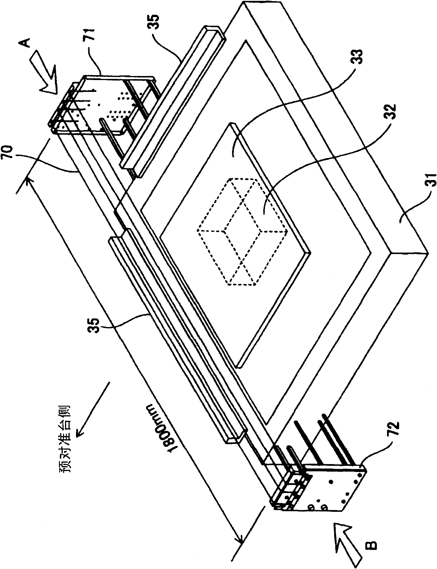
[0056] The light irradiation unit 10 includes a lamp 11 that is a light source that emits light including ultraviolet rays, and a reflector 12 that reflects light from the lamp 11 . In addition, the work table 30 is a flat table using a flat motor, and includes a table plate 31 and a slider (moving body) 32 .

[0057] The ta...


PUM

PropertyMeasurementUnit
lengthaaaaaaaaaa

Abstract

The present invention provides an exposure apparatus which does not damage a workpiece body or the component of the workpiece even when the workpiece falls off from a workpiece conveying mechanism. Furthermore, compared with the prior art, the tact time is not prolonged. The exposure apparatus loads the workpieces conveyed through a manipulator on a workpiece table. Light is irradiated to the workpieces which are loaded on the workpiece table through a mask. The pattern formed on the mask is exposed on the workpieces. The area for conveying the workpiece by the manipulator, namely the space between a conveying height (conveying grade) of the manipulator for conveying workpiece and a surface height of the absorption platform of the workpiece table is paved with a cable which transverses the workpiece table.

Description

technical field [0001] This invention relates to the exposure apparatus which exposes a printed circuit board, the glass substrate for liquid crystal panels, etc. to light. Background technique [0002] Figure 10 An example of the schematic configuration and operation of a conventional exposure apparatus used for patterning wiring and the like in a manufacturing process of a printed circuit board, a liquid crystal panel, etc. (hereinafter also referred to as a workpiece) is shown. [0003] Such an exposure apparatus mainly includes: a light irradiation unit 10; a mask M on which a pattern copied on a workpiece is formed; a mask table 20 holding the mask; and a workpiece W holding a printed circuit board or a liquid crystal panel to be exposed. and a projection lens 40 for projecting the pattern formed on the mask M onto the workpiece W on the workpiece stage 30 . In addition, there is also an exposure apparatus that does not include the projection lens 40 and exposes the m...

Claims


Application Information

Patent Timeline
Patent Type & Authority Applications(China)
IPC IPC(8): G03F7/20
CPCG03F7/70808G03F7/70825G03F7/70991H01L21/67379
Inventor 小池雄辉冈野达广佐藤善彦
Owner USHIO DENKI KK
Why Eureka
Try Eureka