Embedded wireless access device
A wireless access device and access device technology, applied in the direction of wireless communication, devices with flexible lead wires, data exchange details, etc., can solve the problems of inconvenient charging of mobile phones with data lines, loss of network cables, unfavorable use, etc., to achieve Simple structure, avoid poor contact or damage, and ensure the effect of normal use
- Summary
- Abstract
- Description
- Claims
- Application Information
AI Technical Summary
Problems solved by technology
Method used
Image
Examples
Embodiment 1
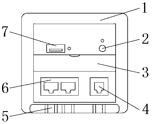
[0019] like figure 1 image 3 As shown in the figure, an embedded wireless access device includes an access device main body 1, the front outer surface of the access device main body 1 is provided with a restart button 2 and a USB interface 7, the restart button 2 is located on one side of the USB interface 7, and the restart button The lower end of the button 2 is provided with a data line storage structure 3, the lower end of the data line storage structure 3 is provided with a main line interface 4 and a branch line interface 6, the main line interface 4 is located on one side of the branch line interface 6, and the lower end of the branch line interface 6 is provided with Network cable limit structure 5.
Embodiment 2
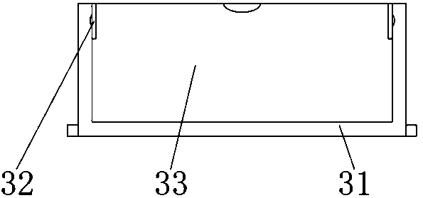
[0021] On the basis of Example 1, as figure 2 As shown, the data cable storage structure 3 includes a data cable storage box 31, a limit block 32 and a fluorescent door panel 33. The front outer surface of the data cable storage structure 3 is provided with a fluorescent door panel 33, and the rear outer surface of the fluorescent door panel 33 is provided with a fluorescent door panel 33. The data cable storage box 31 is provided with a limit block 32 between the data cable storage box 31 and the fluorescent door panel 33, so that when people go out and the battery of the mobile phone is insufficient, people can open the fluorescent door panel 33, and the data cable storage box 31 will be stored in the interior of the data cable storage box 31. The data cable is taken out for charging, and after use, it is convenient for people to continue to store the data cable in the data cable storage box 31, so that the people behind can continue to use it.
Embodiment 3
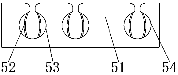
[0023] On the basis of Embodiment 1 and Embodiment 2, as image 3 As shown, the network cable limit structure 5 includes a limit plate 51, a clamping strip 52, a branch line limit slot 53 and a main line limit slot 54, and a limit plate 51 is arranged in the middle of the network cable limit structure 5. The outer surface of the middle part is provided with a branch line limit groove 53 and a voice main line limit groove 54. The main line limit groove 54 is located on one side of the branch line limit groove 53, and the clamping strip 52 is located on the inner surface of the branch line limit groove 53. The connected network cable is clamped inside the branch limit slot 53 and the main line limit slot 54, and then the outer sheath of the network cable is clamped by the clamping strip 52 to limit the position of the network cable, so as to avoid poor contact or damage caused by pulling the network cable, and ensure the equipment normal use.
PUM
 Abstract
Description
Claims
Application Information
 - R&D
- Intellectual Property
- Life Sciences
- Materials
- Tech Scout
- Unparalleled Data Quality
- Higher Quality Content
- 60% Fewer Hallucinations
Browse by: Latest US Patents, China's latest patents, Technical Efficacy Thesaurus, Application Domain, Technology Topic, Popular Technical Reports.
© 2025 PatSnap. All rights reserved.Legal|Privacy policy|Modern Slavery Act Transparency Statement|Sitemap|About US| Contact US: help@patsnap.com


