Sand box for metal casting

A metal casting and sandbox technology, applied in casting molding equipment, metal processing equipment, mold boxes, etc., can solve the problems of insufficient sandbox connection, damaged bolts, inability to disassemble, etc., to achieve structural strength compliance and improve heat dissipation efficiency , The effect of preventing the phenomenon of lifting the box

Active Publication Date: 2020-04-10
阳春市科能实业有限公司
View PDF6 Cites 3 Cited by
  • Summary
  • Abstract
  • Description
  • Claims
  • Application Information

AI Technical Summary

Problems solved by technology

[0003] The joints of the existing sandboxes used for metal casting are not strong enough, and the phenomenon of lifting the box is easy to occur during pouring, resulting in scrapped castings. Some sandboxes are connected by bolts at the joints. Although the connection is reliable, molten iron is easy to splash onto the On the thread of the bolt, the bolt is damaged and cannot be disassembled

Method used


Image

  • Sand box for metal casting
  • Sand box for metal casting
  • Sand box for metal casting

Examples


Embodiment 1

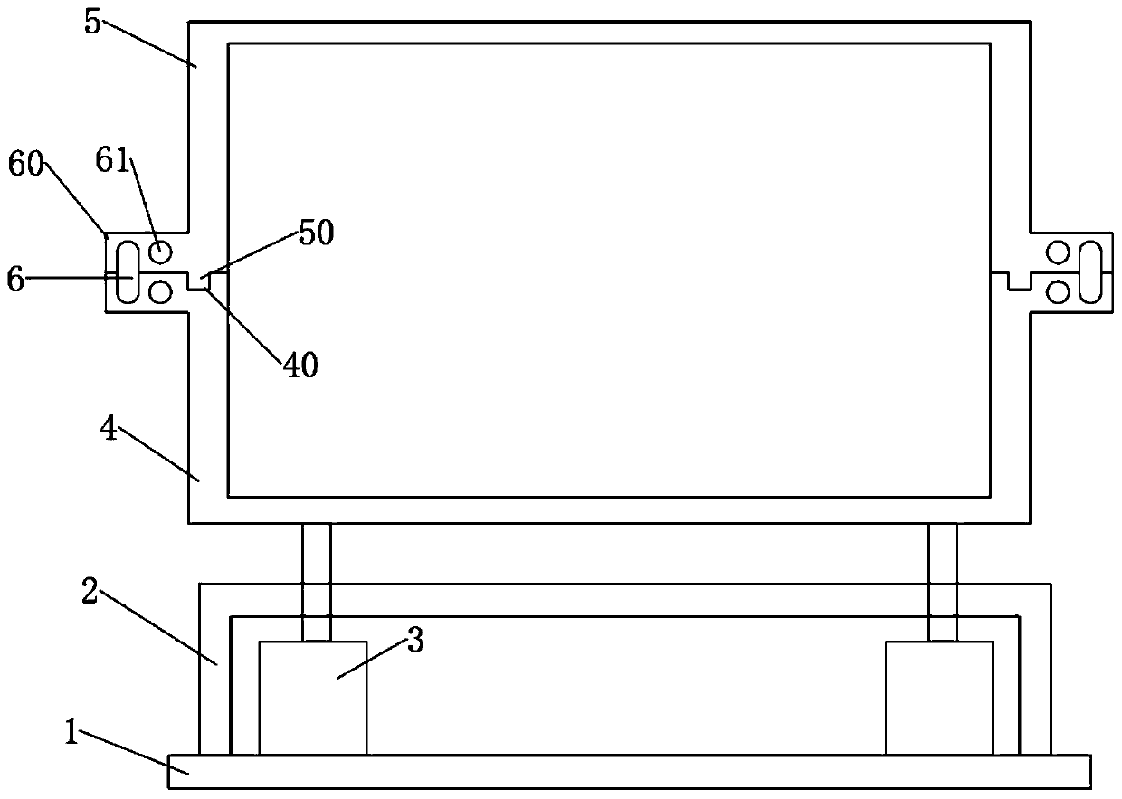
[0026] Such as Figure 1-5 As shown, a sandbox for metal casting includes a base 1 on which a support plate 2 is fixed, the support plate 2 is rectangular in design, the hydraulic column 3 is fixedly connected to the lower casing 4, and the The lower casing 4 is connected with the upper casing 5, and the lower casing 4 and the upper casing 5 are provided with a fixing flange 60 at the junction, and the fixing flange 60 is provided with a fixing hole 61, and the fixing hole 61 A U-shaped collar 6 is plugged in.

[0027] Specifically, a fixing flange 60 is provided at the junction of the upper casing 5 and the lower casing 4, and by setting a fixing hole 61 in the horizontal direction of the fixing flange 60, the U-shaped collar 6 is inserted through the fixing hole 61, so that The upper shell 5 and the lower shell 4 are reliably connected.

[0028] Further, the upper housing 5 is provided with a positioning block 50, and the lower housing 4 is provided with a positioning slot...

Embodiment 2

[0038] This embodiment is a further improvement and limitation of embodiment 1 on the basis of embodiment 1.

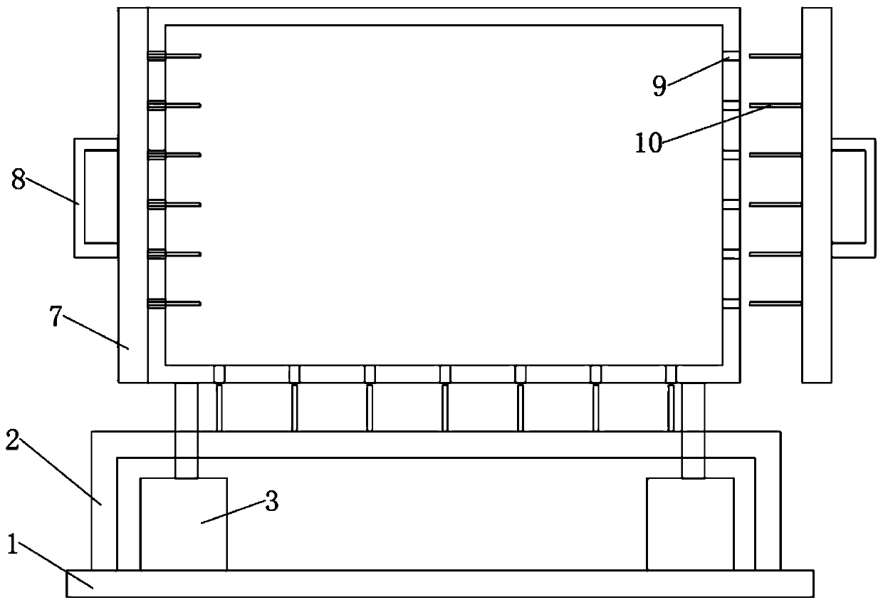
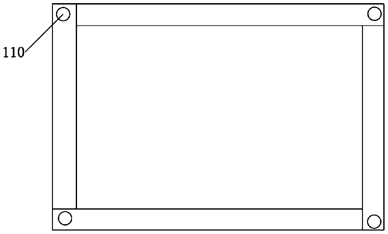
[0039] Such as Figure 1-5 As shown, a sandbox for metal casting includes a base 1, a support plate 2 is fixed on the base 1, the support plate 2 is rectangular in design, hydraulic columns 3 are evenly arranged in the support plate 2, and the The hydraulic column 3 is fixedly connected with the lower casing 4, and the bottom of the lower casing 4 is evenly provided with air holes 9, and the support plate 2 is provided with thin rods 10 at the corresponding positions of the air holes 9, and the lower casing 4 Connected with the upper casing 5, the lower casing 4 and the upper casing 5 are provided with a fixing flange 60 at the joint, and the fixing flange 60 is provided with a fixing hole 61, and the fixing hole 61 is inserted with a U-shaped collar 6.

[0040] Specifically, the upper shell 5 and the lower shell 4 are placed on the support plate 2 in the initial st...


PUM


Abstract

The invention discloses a sand box for metal casting, relates to the technical field of metal casting, and mainly solves the problem of weak connecting places in a traditional sand box. The sand box comprises a base; a support plate is arranged on the base; the support plate is designed as a rectangle; hydraulic columns are uniformly arranged in the support plate; the hydraulic columns are fixedly connected with a lower shell; the lower shell is connected with an upper shell; a fixed flange is arranged in the connected place of the lower shell and the upper shell; a fixed hole is formed in the fixed flange; an U type clamping ring is inserted in the fixed hole; ventilation plates are mounted on the front side and the back side of the lower shell; ventilation holes are uniformly arranged on the front and back sides of the upper shell and the lower shell; fine rods are uniformly distributed on the ventilation plates; and the ventilation plates are connected with the upper shell and thelower shell through the ventilation holes and the fine rods. Through the structure, the connecting reliability of the sand box is effectively improved, and the box hoisting and connected place waste phenomenon is prevented.

Description

technical field [0001] The invention relates to the technical field of metal casting equipment, in particular to a sandbox for metal casting. Background technique [0002] Sandboxes are often used in foundry companies to produce accessories. Traditional sandboxes require manual molding by master workers. The molding process is all done by hand or hand tools. Manual molding is flexible in operation, wide in adaptability, simple in process equipment, and low in cost. [0003] The joints of the existing sandboxes used for metal casting are not strong enough, and the phenomenon of lifting the box is easy to occur during pouring, resulting in scrapped castings. Some sandboxes are connected by bolts at the joints. Although the connection is reliable, molten iron is easy to splash onto the On the thread of the bolt, the bolt is damaged and cannot be disassembled. Contents of the invention [0004] The purpose of the embodiment of the present invention is to provide a sandbox for...

Claims


Application Information

Patent Timeline
Patent Type & Authority Applications(China)
IPC IPC(8): B22C21/08B22C21/10B22C21/12B22C21/02
CPCB22C21/02B22C21/08B22C21/10B22C21/12
Inventor 梁祺
Owner 阳春市科能实业有限公司
Why Eureka
Try Eureka