
Detachable stapler arranging plate structure

A technology for a stapler and a finishing board, which is applied to staple U-shaped nail tools, nailing tools, manufacturing tools, etc., can solve the problems affecting the aesthetics and binding firmness, inconvenient disassembly of the stapler and the finishing board, and the distance between binding points. It is not easy to grasp and other problems, so as to achieve the effect of improving aesthetics, quick disassembly and assembly, and even binding

Pending Publication Date: 2020-04-10
XUZHOU UNIV OF TECH
View PDF2 Cites 0 Cited by
  • Summary
  • Abstract
  • Description
  • Claims
  • Application Information

AI Technical Summary

Problems solved by technology

[0004] 1. It is inconvenient to disassemble the stapler and the finishing board. For the binding of a small amount of paper, having a finishing board will cause inconvenience;
[0005] 2. Although the width of the binding point is marked, the spacing of the binding point is not marked, which makes it difficult to grasp the spacing of the binding point, which affects the aesthetics and binding firmness

Method used


Image

  • Detachable stapler arranging plate structure
  • Detachable stapler arranging plate structure
  • Detachable stapler arranging plate structure

Examples


Embodiment 1

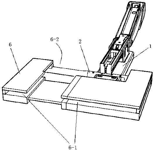
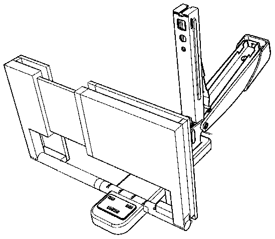
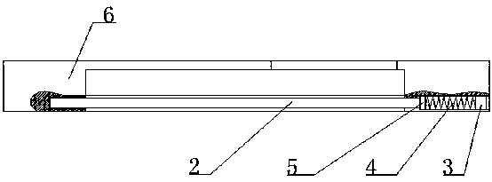
[0021] like figure 1 and figure 2 As shown, a detachable stapler finishing board structure includes a stapler 1 and a finishing board 6;

[0022] The binding end of the stapler 1 is provided with a sliding hole 1-1 perpendicular to the stapler 1; the upper side of the sliding hole 1-1 intersects with the upper surface connected to the binding end, and the upper side of the sliding hole 1-1 forms an open indication slot 1-2;

[0023] Have the finishing groove 6-1 that is used to place paper on the finishing board 6, combine figure 2 As shown, the upper side of the finishing slot 6-1 is open for putting in paper; the binding slot 6-2 is under the finishing plate 6, the binding slot 6-2 communicates with the finishing slot 6-1, and the binding end of the stapler 1 At the position of binding slot 6-2;

[0024] The identification shaft 2 is installed between the two ends of the binding groove 6-2, and the identification shaft 2 is marked with a scale. The identification shaf...

Embodiment 2

[0034] On the basis of the first embodiment above, combined with Figure 4 as shown,

[0035] In order to realize the fast disassembly and assembly of the stapler 1 and the finishing plate 6, the specific structure of the sliding hole 1-1 is:

[0036] Sliding hole 1-1 is divided into fixed part 7 and sliding part 8 from the middle; ; The spring II 9 for pushing the sliding part 8 to the fixed part 7 is connected to the back side of the sliding part 8 .

[0037] Preferably: the binding end of the stapler 1 is provided with a chute 1-3, and the side wall of the chute is provided with a bar-shaped guide groove 1-4; There is a strip guide plate 8-1 that cooperates with the strip guide groove 1-4.

[0038] when using it,

[0039] Slide the sliding part 8 to press against the spring Ⅱ 9, so that the indication groove 1-2 is opened and widened;

[0040] Then, put the identification shaft 2 into the sliding hole 1-1 at the fixed part 7;

[0041] Finally, the sliding part 8 is re...


PUM


Abstract

The invention discloses a detachable stapler arranging plate structure, and belongs to the technical field of office and school supplies. A sliding hole is formed in the binding end of a stapler, an open indicating groove is formed in the upper side of the sliding hole, an arranging groove used for containing paper is formed in an arranging plate, a binding groove is formed in the rear end of thearranging plate, an identification shaft is installed between the two ends of the binding groove, scales are marked on the identification shaft, the identification shaft is rotatably installed in thesliding hole of the stapler, and the diameter of the identification shaft is larger than that of the indicating groove. According to the detachable stapler arranging plate structure, the stapler and the arranging plate can be simply and rapidly disassembled and assembled, and use is convenient; in addition, the arranging plate can rotate around the identification shaft, and the arranging plate iserected, so that paper alignment is facilitated; and the scales are arranged on the identification shaft, the distance of binding points can be observed and determined conveniently through the indicating groove, uniform binding can be guaranteed, and attractiveness and binding firmness are improved.

Description

technical field [0001] The invention relates to a stapler, in particular to a detachable stapler finishing plate structure. Background technique [0002] Stapler is a necessary office supplies in our daily work and study. In daily work, we often print or organize loose papers. Stapler can provide a convenient and quick method to bind them together. However, when we use the stapler, the phenomenon of uneven order often occurs, which not only affects the appearance but also affects the actual use. [0003] In order to ensure neat binding, a stapler with a finishing board has appeared in the prior art, such as a slidable stapler disclosed by a Chinese patent and its usage method (CN105856163A), and a paper alignment, positioning, and binding stapler Base (CN107571660A); it is all arranged by a finishing board capable of sorting papers, and then bound by a stapler. The disadvantages of this structure are: [0004] 1. It is inconvenient to disassemble the stapler and the finis...

Claims


Application Information

Patent Timeline
Patent Type & Authority Applications(China)
IPC IPC(8): B25C7/00
CPCB25C7/00
Inventor 刘丽丽施天逸陈跃杨丽娟
Owner XUZHOU UNIV OF TECH
Learn More