Fixed take-up and pay-off cable drum for power panel

A technology for power supply panel, retracting and releasing cables, applied in the field of mobile electrical equipment, can solve the problems of cable insulation shell rupture, affecting equipment use efficiency, cable knotting, etc.

Inactive Publication Date: 2020-04-10
江苏金兰湾电气科技有限公司
View PDF7 Cites 0 Cited by
  • Summary
  • Abstract
  • Description
  • Claims
  • Application Information

AI Technical Summary

Problems solved by technology

[0002] In the existing Chinese patent database, a patent named mobile cable reel is disclosed, the application number is CN201520555611.2, the application date is 2015.07.28, the authorization announcement number is CN204823508U, and the authorization announcement date is 2015.12.02. The device includes support A frame and a reel, the reel is rotatably installed on the support frame, a cable is wound on the reel, a power supply socket is arranged at the end of the reel, and the power socket has at least one power supply connector, and the power connector is electrically connected with the cable, the mobile cable reel also includes an insulating cover plate, the insulating cover plate is set on the power socket, and a through hole is opened on the insulating cover plate, and the through hole is set opposite to the power connector , its shortcoming is that: the panel of this device and the power plug are fixed on the reel, and the panel rotates with the rotation of the reel, which will easily make the cable on the socket itself knotted and cause the cable The insulation shell is broken, which shortens the service life of the cable. In order to prevent the power cord from being tangled, the power tray must be turned off first, the power cord must be unplugged, and then the cable tray should be moved. This not only increases the working time, but also affects the frequent switching equipment. equipment efficiency

Method used


Image

  • Fixed take-up and pay-off cable drum for power panel
  • Fixed take-up and pay-off cable drum for power panel
  • Fixed take-up and pay-off cable drum for power panel

Examples


Embodiment Construction

[0020] The technical solutions described in the present application will be further described below in conjunction with the drawings and embodiments.

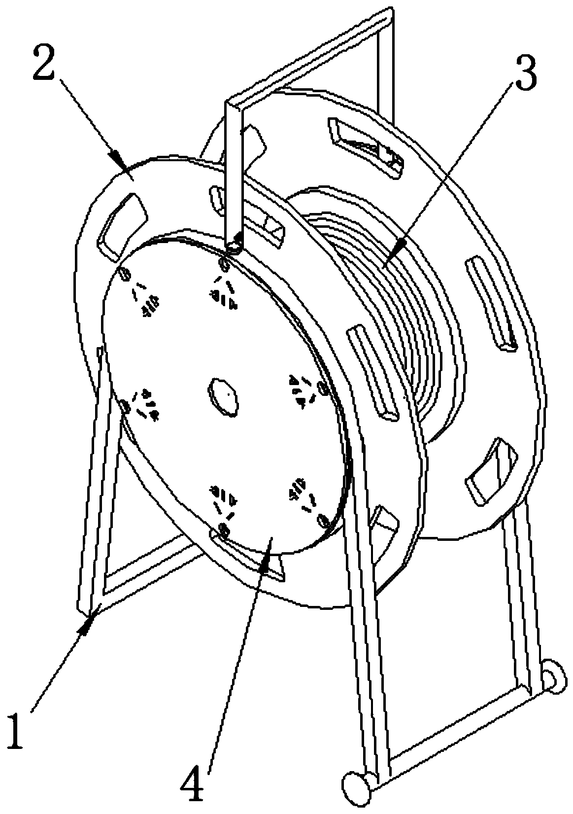
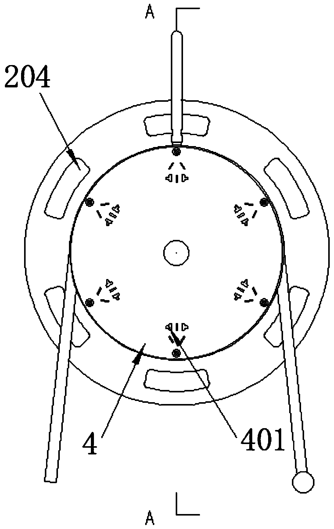
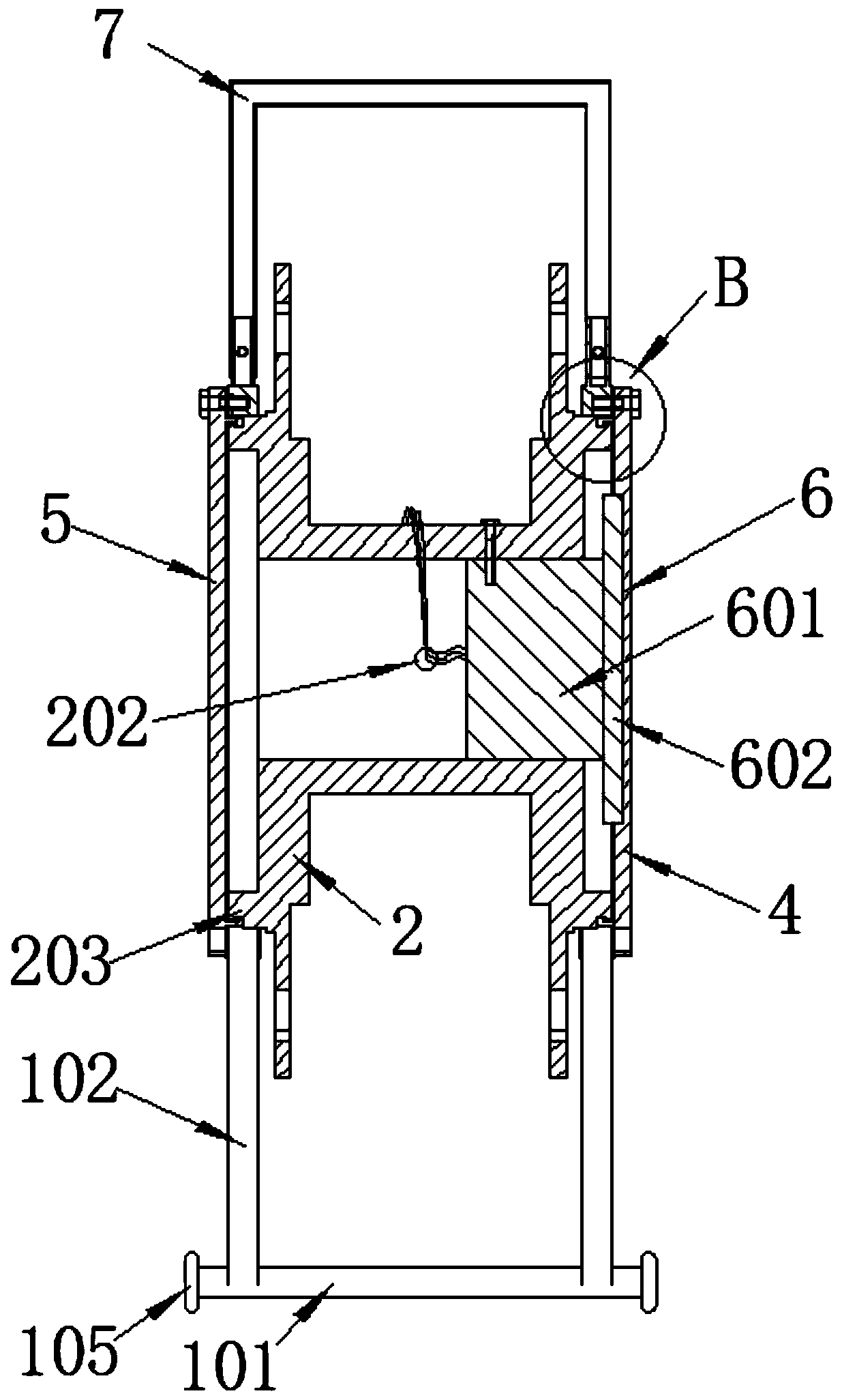
[0021] Such as Figure 1-5 As shown in the figure, it is a fixed reel for receiving and releasing cables on a power panel, including a fixed bracket 1, on which a winding wheel 2 for winding a cable 3 is arranged, and the winding wheel 2 is rotatably connected with the fixed bracket 1, One side of the winding reel 2 is provided with a front panel 4, and multiple groups of power sockets 401 are arranged on the front panel 4, and the other side of the winding reel 2 is provided with a reverse panel 5, and the hollow shaft of the winding reel 2 is provided with a threading socket. The holes 202, the left and right sides of the reel 2 are provided with card slots 201, the front panel 4 and the back panel 5 are provided with claws 402, and the claws 402 of the front panel 4 are engaged with the corresponding card slots 201, so that ...


PUM


Abstract

The invention relates to a fixed take-up and pay-off cable drum for a power panel, which comprises a fixed bracket, a reel, a cable, a front panel and a back panel, and is characterized in that a power socket is arranged on the front panel; a threading hole is formed in the reel; clamping grooves are formed in two outer sides of the reel; clamping jaws are arranged on the front panel and the backpanel; the clamping jaws of the front panel and the back panel are respectively clamped with the corresponding clamping grooves so as to enable the front panel and the back panel to be hinged relativeto the reel; an electric slip ring is arranged in the reel; the rotor end of the electric slip ring is fixedly connected with the reel; the stator end of the electric slip ring is connected with thefront panel; a cable wiring end on the reel is electrically connected with a rotor wire input end of the electric slip ring through the threading hole; and a stator wire output end of the electric slip ring is electrically connected with the power socket. Due to the fact that the panel is hinged to the reel, the panel and the reel are two independent parts and do not move synchronously with each other, the function that the cable rotates at one end of the reel and does not rotate at one end of the power socket on the panel is achieved by means of the arrangement of the electric slip ring.

Description

technical field [0001] The invention belongs to the field of mobile electrical equipment, and in particular relates to a power panel fixedly receiving and releasing cable reels. Background technique [0002] In the existing Chinese patent database, a patent named mobile cable reel is disclosed, the application number is CN201520555611.2, the application date is 2015.07.28, the authorization announcement number is CN204823508U, and the authorization announcement date is 2015.12.02. The device includes support A frame and a reel, the reel is rotatably installed on the support frame, a cable is wound on the reel, a power supply socket is arranged at the end of the reel, and the power socket has at least one power supply connector, and the power connector is electrically connected with the cable, the mobile cable reel also includes an insulating cover plate, the insulating cover plate is set on the power socket, and a through hole is opened on the insulating cover plate, and the...

Claims


Application Information

Patent Timeline
IPC IPC(8): B65H75/14
CPCB65H75/14
Inventor 赵金林
Owner 江苏金兰湾电气科技有限公司
Why Eureka
Try Eureka