Bonding equipment for LED light source module and base

A technology of LED light sources and modules, which is applied in the direction of light sources, lighting and heating equipment, semiconductor devices of light-emitting elements, etc., can solve problems such as easy to stick to hands, difficult to clean, assembly speed, low error rate, etc., to achieve the goal of using The effect of speed and efficiency improvement

Active Publication Date: 2021-06-25
邵小祥
View PDF0 Cites 0 Cited by
  • Summary
  • Abstract
  • Description
  • Claims
  • Application Information

AI Technical Summary

Problems solved by technology

[0004] In order to overcome the shortcomings of the current assembly of the light source board base and the light source board module, there are many manual processes, the speed is slow and error-prone, and it is easy to stick to the hand and difficult to clean. Therefore, the technical problem of the present invention is: to provide a Bonding equipment for LED light source modules and bases with fast assembly speed, low error rate, and no sticking to hands

Method used


Image

  • Bonding equipment for LED light source module and base
  • Bonding equipment for LED light source module and base
  • Bonding equipment for LED light source module and base

Examples


Embodiment 1

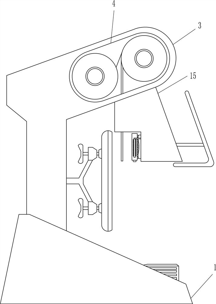
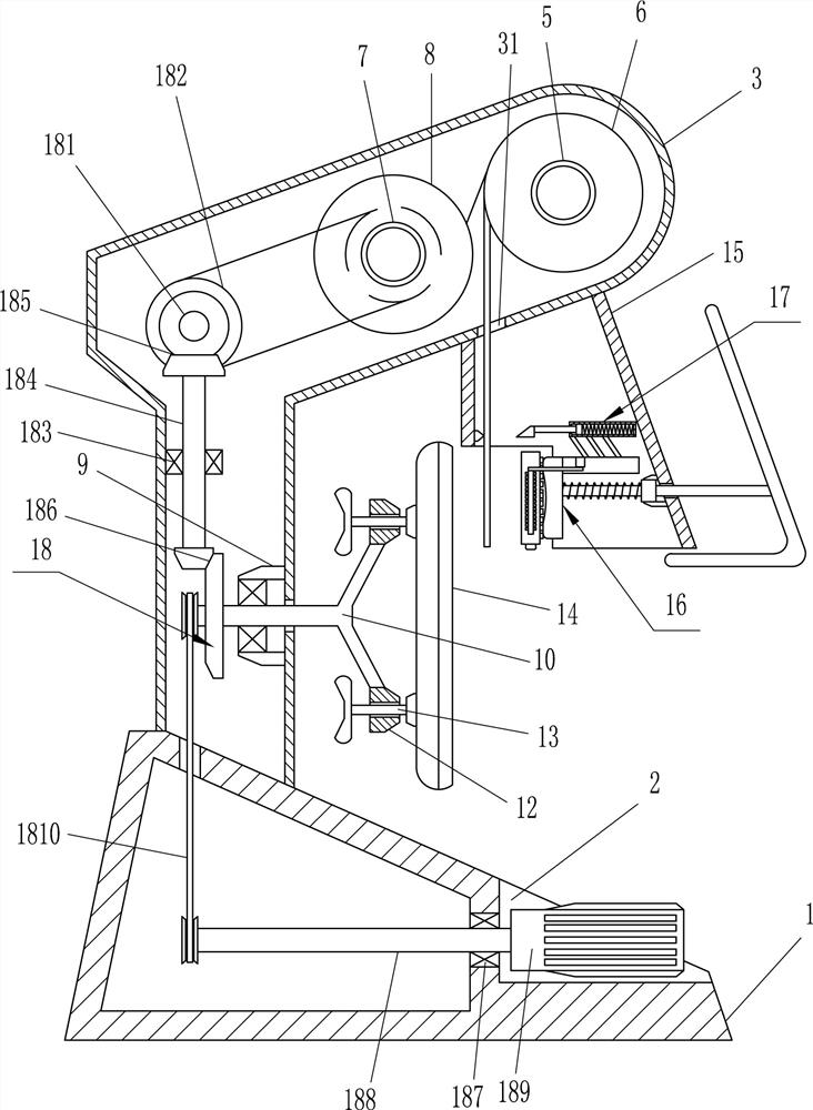
[0019]A kind of bonding equipment of LED light source module and base, such as Figure 1-2 As shown, it includes a mounting seat 1, a mounting box 3, a first rotating shaft 5, a second rotating shaft 7, a recovery cylinder 8, a first bearing seat 9, a rotating frame 10, a nut 12, a screw rod 13, a connection box 15, and a moving fitting The device 16 and the glue cutting device 17, the installation base 1 is used to install the internal parts of the equipment and place the equipment stably, the installation box 3 is used to install the internal parts of the equipment, the connection box 15 is used to install the internal parts of the equipment, and the mobile sticker The combining device 16 is used to bond the light source board module 1612, and the glue cutting device 17 is used to cut off the double-sided sticker 6, specifically:

[0020] The right side of the mounting base 1 is provided with a triangular groove 2, the upper side of the mounting base 1 is provided with a mou...

Embodiment 2

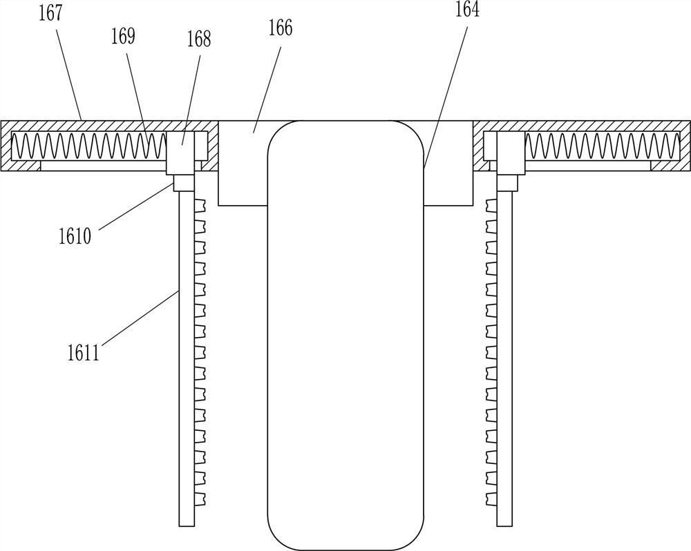
[0023] On the basis of Example 1, such as Figure 3-4 As shown, the mobile fitting device 16 includes a guide sleeve 161, a guide rail 162, a moving frame 163, a rubber plate 164, a first elastic member 165, a mounting rod 166, a first slide rail 167, a first slider 168, a first Two elastic parts 169, extension rod 1610 and pressure rod 1611, specifically:

[0024] The right side wall of the connection box 15 is provided with a guide sleeve 161, and a guide rail 162 is slidably connected to the inside of the guide sleeve 161. The right end of the guide rail 162 is connected with a moving frame 163, and the left end of the guide rail 162 is connected with a rubber plate 164. The left side of the guide sleeve 161 is connected with a first elastic member 165, the left side of the first elastic member 165 is connected to the right side of the rubber plate 164, and the upper right side of the rubber plate 164 is provided with a mounting rod 166. The front and rear sides of the rod...

Embodiment 3

[0027] On the basis of Example 2, such as image 3 As shown, the glue cutting device 17 includes a support rod 171, a second slide rail 172, a second slider 173, a third elastic member 174, a moving rod 175, a movable pointed plate 176 and a fixed pointed plate 177, specifically for:

[0028] The upper side of the mounting rod 166 is connected with a support rod 171, the upper end of the support rod 171 is connected with a second slide rail 172, and the second slide rail 172 is slidably connected with a second slide block 173, and the second slide rail 172 is connected with a second slide block 173. The right side of the block 173 is connected with a third elastic member 174, the right side of the third elastic member 174 is connected to the right side of the second slide rail 172, and the left side of the second slide block 173 is connected with a moving rod 175, so A movable pointed plate 176 is connected to the left end of the moving rod 175, and a fixed pointed plate 177 ...


PUM


Abstract

The invention relates to assembly of a light source board, in particular to a bonding device for an LED light source module and a base. The technical problem to be solved is how to provide a bonding device for an LED light source module and a base that can be assembled quickly, has a low error rate, and does not stick to hands. A bonding device for an LED light source module and a base, including a mounting base, a mounting box, etc.; a triangular groove is formed on the right side of the mounting base, and a mounting box is provided on the upper side of the mounting base. The present invention is by adopting that double-sided self-adhesive tape is enclosed within on the first rotating shaft, and has added the reclaiming cylinder that can reclaim the paper tape of double-sided self-adhesive tape, and drives the rubber strip of double-sided self-adhesive tape to The way to use it by moving it down can prevent the double-sided self-adhesive tape from sticking to people's hands, and the speed and efficiency of use can be improved.

Description

technical field [0001] The invention relates to assembly of a light source board, in particular to a bonding device for an LED light source module and a base. Background technique [0002] At present, when assembling the light source board, especially when assembling the LED light source module and the light source board base, many of them are manually carried out, that is, manually holding the light source board module and double-sided self-adhesive tape. It is necessary to manually tear off a certain length of double-sided self-adhesive tape, and manually glue it on the back of the light source board module, and then glue the light source board module to the light source board base, but the problem with this is that the speed is very slow , and there are many processes, resulting in a high error rate, and when the double-sided sticker is bonded to the back of the light source board module, it is easy to stick to the hands and difficult to clean. [0003] In view of this, ...

Claims


Application Information

Patent Timeline
Patent Type & Authority Patents(China)
IPC IPC(8): F21K9/90F21Y115/10
CPCF21K9/90F21Y2115/10
Inventor 刘佩瑶
Owner 邵小祥
Why Eureka
Try Eureka