Distributed coherent radar angle measurement method

A coherent radar and distributed technology, applied to radio wave measurement systems, instruments, etc., can solve problems such as low accuracy, ambiguity in angle measurement, and high-precision angle estimation without ambiguity, and achieve high-precision estimation and release of angle measurement blur effect

Active Publication Date: 2020-04-10
THE 724TH RES INST OF CHINA SHIPBUILDING IND
View PDF8 Cites 1 Cited by
  • Summary
  • Abstract
  • Description
  • Claims
  • Application Information

AI Technical Summary

Problems solved by technology

[0004] The purpose of the present invention is to overcome the shortcomings of ambiguity and low pr

Method used


Image

  • Distributed coherent radar angle measurement method
  • Distributed coherent radar angle measurement method
  • Distributed coherent radar angle measurement method

Examples


Embodiment Construction

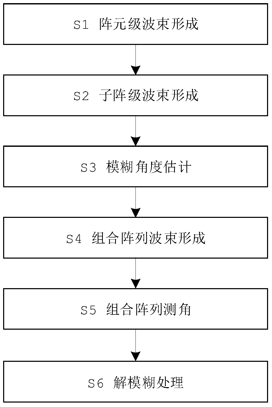
[0017] Implementation process of the present invention and information processing such as figure 2 As shown, the specific description is the following process:

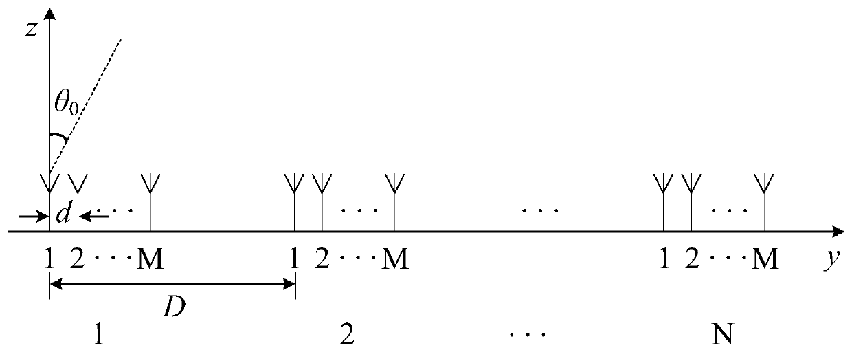
[0018] S1 element-level beamforming: one-dimensional distributed linear array structure such as figure 1 As shown, the number of sub-arrays is N, and each sub-array is a uniform linear array composed of M array elements, M and N are both even numbers, the inter-array spacing d=λ / 2, and the sub-array spacing is D , the target incident angle is θ 0 . In receive coherent mode, all transmitting units transmit the same signal and achieve in-phase superposition at the target. Assuming that the signal envelope after being reflected by the target can be expressed as a(t), assuming that the mth (m=1,2 ..., M) Delay τ of array elements nm It can be expressed as:

[0019]

[0020] Among them, r 11 Indicates the delay of the first element of the first sub-array, and c indicates the propagation speed of electromagnetic ...


PUM


Abstract

The invention relates to a distributed coherent radar angle measurement method. Aiming at the problem of angle measurement ambiguity caused by grating lobe influence of beams of a distributed array, high-precision measurement and ambiguity resolution are carried out on an angle by adopting a plurality of combined array methods. The method comprises the specific steps of (1) array element level beam forming, (2) sub-array level beam forming, (3) fuzzy angle estimation, (4) combined array DBF, (5) combined array angle estimation and (6) ambiguity resolution processing, and can carry out ambiguity resolution processing on a monopulse phase ratio measurement angle to obtain a high-precision ambiguity-free angle estimation value.

Description

technical field [0001] The invention relates to the technical field of sparse array angle measurement. Background technique [0002] In recent years, with the continuous expansion of the application field and the deepening of the application level, large-aperture radars are difficult to meet the needs of modern battlefield operations due to their shortcomings such as poor mobility and low cost-effectiveness. Lincoln Laboratory proposed the concept of distributed coherent radar in 2003 and took it as the direction of the next-generation ballistic missile defense system. Its core idea is to carry out signal coherent fusion with small and distributed radar or array antenna to achieve the detection performance of large aperture radar. Distributed coherent radar is the crystallization of the idea of ​​"dividing the whole into parts". Compared with large-aperture radars, distributed coherent radars can move quickly, change positions in time, and have strong survivability. At th...

Claims


Application Information

Patent Timeline
IPC IPC(8): G01S7/41
CPCG01S7/411
Inventor 涂刚毅王雪琦吴少鹏
Owner THE 724TH RES INST OF CHINA SHIPBUILDING IND
Why Eureka
Try Eureka