
A marine meteorological observation device

A technology for meteorological observation and equipment, which is applied to measurement devices, surveying and navigation, and open-air water source surveying, etc., can solve problems such as failure of electronic devices, collision damage, paralysis of observation equipment, etc., and achieve the effect of reasonable structural design.

Active Publication Date: 2021-09-28
国家海洋局北海海洋环境监测中心站
View PDF0 Cites 0 Cited by
  • Summary
  • Abstract
  • Description
  • Claims
  • Application Information

AI Technical Summary

Problems solved by technology

[0002] Fixed-point observations are mostly used in marine meteorological observations and marine hydrological observations. Moored buoys are moored at designated locations through cables and anchorage systems to achieve fixed-point observations. There are usually many large oceans in coastal and offshore waters. Meteorological monitoring buoys, in these marine meteorological monitoring buoys, are often equipped with a large number of valuable instruments and equipment for monitoring water quality, hydrology and meteorology, etc., and there are often floating objects and waves on the sea surface, which will affect the testing equipment Cause certain damage, once the buoy body collides, it will easily cause the internal electronic devices to fail, cause the observation equipment to be paralyzed, affect the meteorological observation, and cause huge economic losses. At present, the stability of the traditional marine meteorological observation buoy is relatively poor , in severe sea conditions, it is easy to be damaged by collision. The existing marine meteorological observation buoys do not have the anti-collision function. Poor, for this reason, we propose a marine meteorological observation equipment

Method used


Image

  • A marine meteorological observation device
  • A marine meteorological observation device
  • A marine meteorological observation device

Examples


Embodiment Construction

[0018] The following will clearly and completely describe the technical solutions in the embodiments of the present invention with reference to the accompanying drawings in the embodiments of the present invention. Obviously, the described embodiments are only some, not all, embodiments of the present invention. Based on the embodiments of the present invention, all other embodiments obtained by persons of ordinary skill in the art without making creative efforts belong to the protection scope of the present invention.

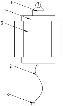
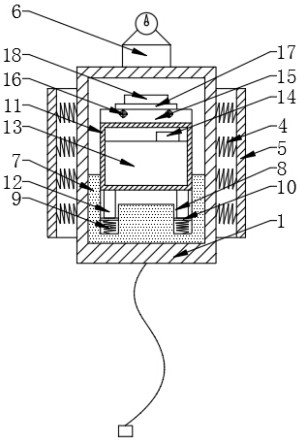
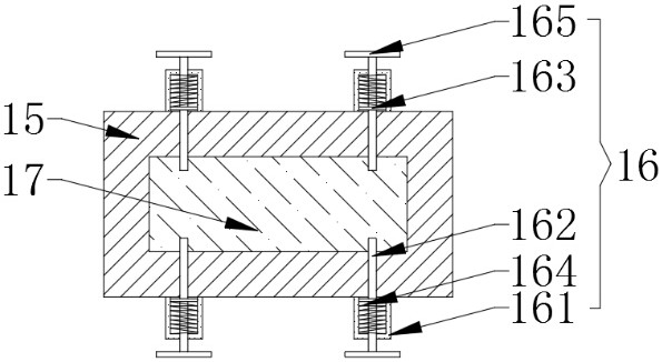
[0019] see figure 1 with figure 2 , the present invention provides a technical solution: a marine meteorological observation equipment, comprising an outer protective shell 1, the bottom of the outer protective shell 1 is fixedly equipped with a mooring line 2, and the bottom end of the mooring line 2 is fixedly equipped with a grasping anchor 3 , the outer wall of the outer protective shell 1 is fixedly equipped with first support springs 4 around, and the ...


PUM


Abstract

The invention discloses a marine meteorological observation equipment in the technical field of marine meteorological observation equipment. The inner bottoms of the two groups of buffer tanks are fixedly connected with second support springs, and the top ends of the second support springs are fixedly equipped with movable plates. The left and right sides of the bottom of the protection box are fixedly provided with guide columns connected to the top of the movable plate, the top of the battery is electrically connected to a single-chip controller, the top of the protection box is fixedly equipped with a positioning seat, and the positioning seat The front and rear side walls are fixedly equipped with stoppers, the top of the positioning seat is movably plugged with a sensor mount that is compatible with the stopper, and the top of the sensor mount is movable and screwed with a protective cover, which can The device realizes the double protection of the exterior and interior, improves the anti-collision and anti-vibration capabilities of the device, can quickly realize the fixed assembly of the positioning seat and the sensor mounting seat, and facilitates the installation of the sensor and facilitates later maintenance and replacement.

Description

technical field [0001] The invention relates to the technical field of marine meteorological observation equipment, in particular to a marine meteorological observation equipment. Background technique [0002] Fixed-point observations are mostly used in marine meteorological observations and marine hydrological observations. Moored buoys are moored at designated locations through cables and anchorage systems to achieve fixed-point observations. There are usually many large oceans in coastal and offshore waters. Meteorological monitoring buoys, in these marine meteorological monitoring buoys, are often equipped with a large number of valuable instruments and equipment for monitoring water quality, hydrology and meteorology, etc., and there are often floating objects and waves on the sea surface, which will affect the testing equipment Cause certain damage, once the buoy body collides, it will easily cause the internal electronic devices to fail, cause the observation equipmen...

Claims


Application Information

Patent Timeline
Patent Type & Authority Patents(China)
IPC IPC(8): G01W1/00G01C13/00
CPCG01C13/00G01W1/00
Inventor 张春华李少朗
Owner 国家海洋局北海海洋环境监测中心站
Learn More