
Migration method and migration device

A technology for electronic equipment to be migrated, applied in the direction of instruments, input/output to record carriers, computing, etc., can solve the problems of insufficient intelligent experience and cumbersome operation steps, and achieve the effect of improving intelligence and migration efficiency

Active Publication Date: 2020-04-10
LENOVO (BEIJING) CO LTD
View PDF16 Cites 1 Cited by
  • Summary
  • Abstract
  • Description
  • Claims
  • Application Information

AI Technical Summary

Benefits of technology

This technology allows for efficient movement between different devices without requiring them to have their own memory or storage space. It achieves this by identifying objects with which they belong together before moving it around again.

Problems solved by technology

The technical problem addressed by this patented technology relates to how easy it becomes difficult for users who want to move data from their own computer into others' computers without having to manually search through irrelevant documents before moving them back again.

Method used


Image

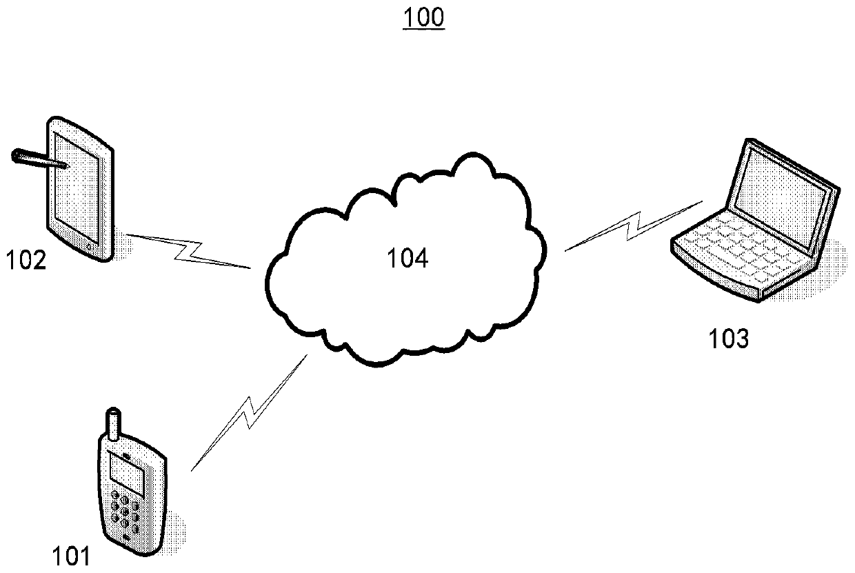
  • Migration method and migration device
  • Migration method and migration device
  • Migration method and migration device

Examples


Embodiment Construction

[0033] Hereinafter, embodiments of the present disclosure will be described with reference to the drawings. It should be understood, however, that these descriptions are exemplary only, and are not intended to limit the scope of the present disclosure. In the following detailed description, for purposes of explanation, numerous specific details are set forth in order to provide a thorough understanding of the embodiments of the present disclosure. It may be evident, however, that one or more embodiments may be practiced without these specific details. Also, in the following description, descriptions of well-known structures and techniques are omitted to avoid unnecessarily obscuring the concepts of the present disclosure.

[0034] The terminology used herein is for the purpose of describing particular embodiments only, and is not intended to be limiting of the present disclosure. The terms "comprising", "comprising", etc. used herein indicate the presence of stated features,...


PUM


Abstract

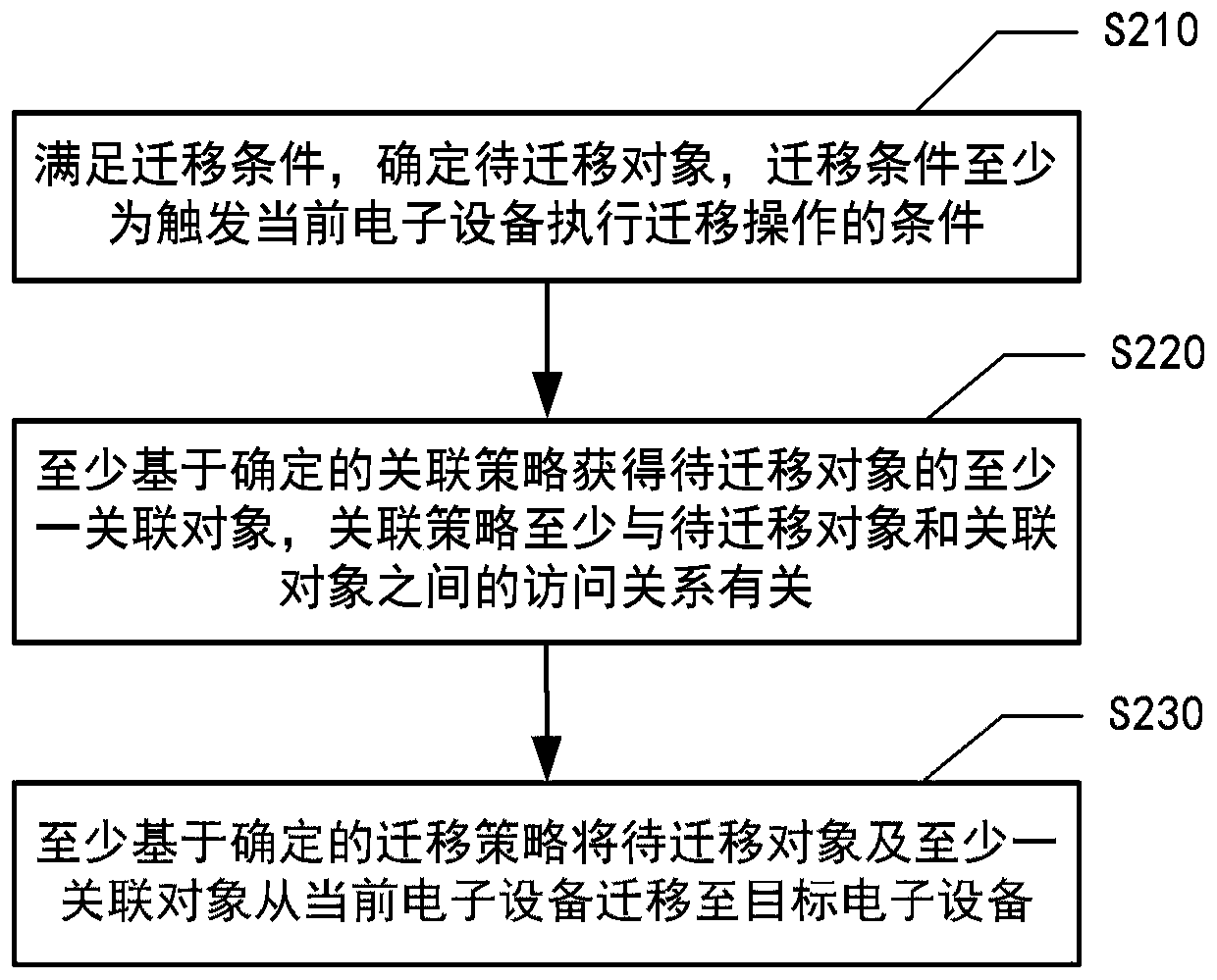
The invention provides a migration method which includes the steps: satisfying a migration condition, determining a to-be-migrated object, obtaining at least one associated object of the to-be-migrated object at least based on a determined association strategy which is at least related to an access relationship between the to-be-migrated object and the associated object, and migrating the to-be-migrated object and the at least one associated object from a current electronic device to a target electronic device at least based on the determined migration strategy, wherein the migration conditionis at least a condition for triggering the current electronic device to execute a migration operation. In addition, the invention further provides a migration device.

Description


Claims


Application Information

Patent Timeline
Owner LENOVO (BEIJING) CO LTD
Learn More