Handle pop-up structure of change-over switch

A technology for changing switches and handles, which is applied in the direction of electric switches, electrical components, circuits, etc., which can solve the problems of easy loss, easy forgetting to put back, increase product dimensions, etc., and achieve the effect of avoiding loss

Active Publication Date: 2020-04-10
SCHNEIDER WINGOAL TIANJIN ELECTRIC EQUIP
View PDF2 Cites 0 Cited by
  • Summary
  • Abstract
  • Description
  • Claims
  • Application Information

AI Technical Summary

Problems solved by technology

[0002] The operating handles of the existing transfer switches are placed in various ways, some are placed in the accessory bag, which is easy to lose; some are placed on the side of the body, which not only increases the overall size of the product, but also is difficult to handle. It is easy for the user to forget to put the switch back after operating the switch, and the handle is still easy to lose; and no matter which placement method, the user needs to find out where the handle is before operating the switch.

Method used


Image

  • Handle pop-up structure of change-over switch
  • Handle pop-up structure of change-over switch
  • Handle pop-up structure of change-over switch

Examples


Embodiment 1

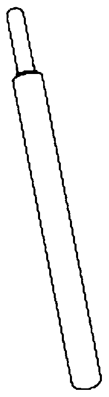
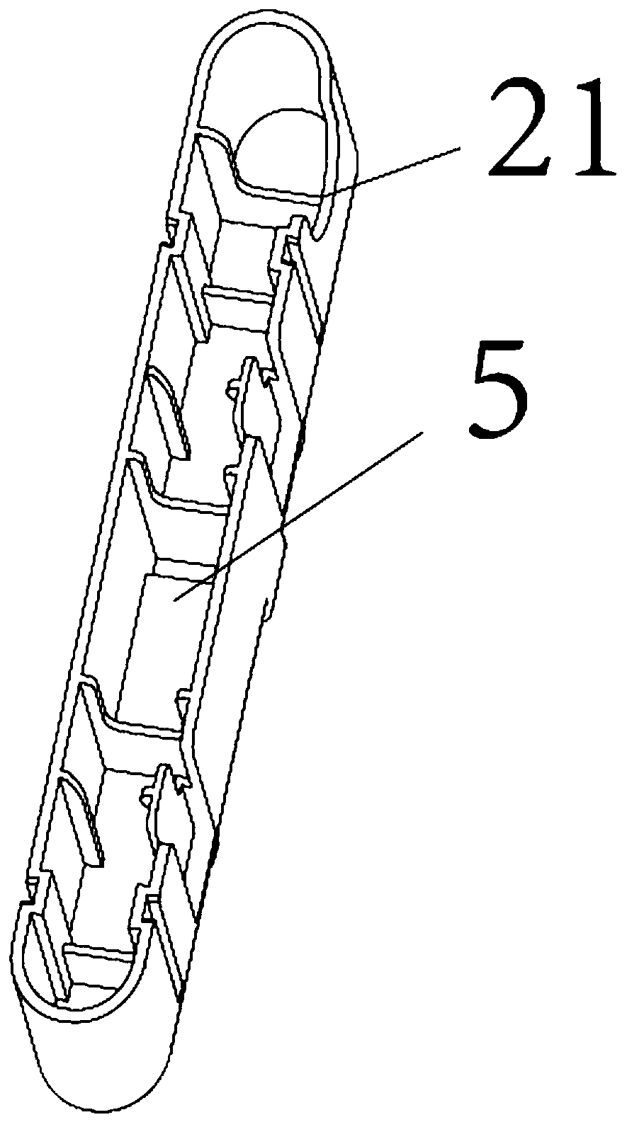
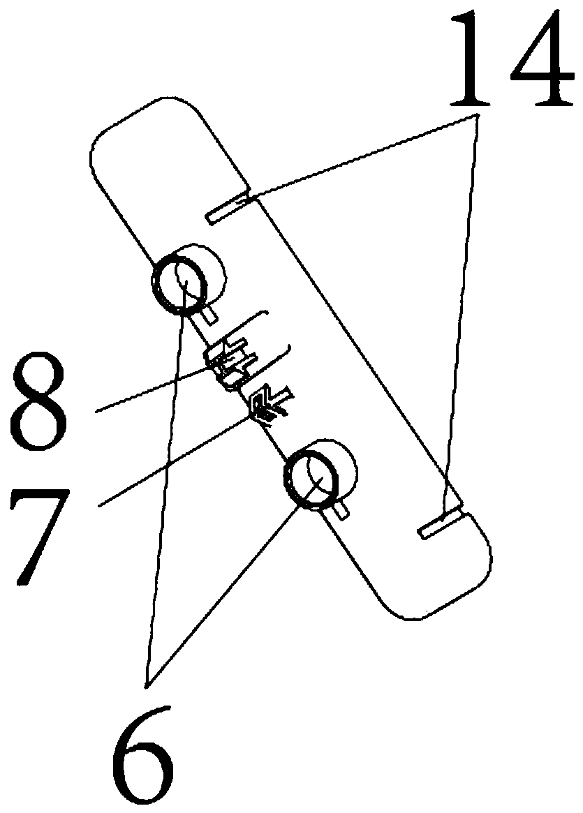
[0041] Such as Figure 1-19As shown, the handle pop-up structure of a transfer switch provided by this embodiment includes an upper case 1, a manual and automatic sliding cover, a handle box, a handle, a slide plate, a fixing member, and a spring; the upper surface of the upper case 1 is provided with a manual and automatic The slide cover sliding area 2, the manual automatic slide cover sliding area 2 is provided with a handle box warehouse 3 and a pair of guide grooves 4, the upper surface of the handle box forms a groove-shaped handle warehouse 5, and the bottom of the handle box is provided with at least A pair of spring bins 6, a first buckle 7 and a second buckle 8 are arranged between the spring bins 6, and the height of the end of the second buckle 8 from the bottom of the handle box is higher than that of the first buckle 7 The height of the bottom of the handle box; the bottom surface of the manual automatic sliding cover is provided with a pair of sliding columns 9;...


PUM


Abstract

The invention relates to a handle pop-up structure of a change-over switch. A handle box bin and a pair of guide grooves are formed in the upper surface of an upper shell, a handle bin is formed in ahandle box, at least one pair of spring bins are arranged at the bottom of the handle box, a first buckle and a second buckle are arranged between the spring bins, and the height from the tail end ofthe second buckle to the bottom of the handle box is larger than that from the first buckle to the bottom of the handle box; a pair of sliding columns are arranged on the bottom surface of the manual-automatic sliding cover; and a pair of connecting holes, a first sliding groove and a second sliding groove are formed in the sliding plate in a penetrating mode. Spring fixing columns are arranged onthe surfaces of the fixing pieces; a handle locates in handle bin, and the handle box is positioned in the handle box bin; and the manual-automatic sliding cover is located on the surface of the manual-automatic sliding cover sliding area, the sliding column freely penetrates through the guide groove, the other end of the sliding column is fixedly connected with the sliding plate, the first buckle and the second buckle can penetrate through or disengage from the first sliding groove and the second sliding groove, the fixing piece is fixedly connected with the bottom of the handle box bin, andthe two ends of the spring are limited by the spring bin and the spring fixing column. The handle is closer to the use feeling of customers, and loss of the handle is avoided.

Description

technical field [0001] The invention belongs to the technical field of a transfer switch operating mechanism, and in particular relates to a handle pop-up structure of a transfer switch. Background technique [0002] The operating handles of the existing transfer switches are placed in various ways, some are placed in the accessory bag, which is easy to lose; some are placed on the side of the body, which not only increases the overall size of the product, but also is difficult to handle. It is easy for the user to forget to put it back after operating the switch, and the handle is still easy to lose; and no matter which placement method, the user needs to find out where the handle is before operating the switch. [0003] Therefore, based on these problems, it is of great practical significance to provide a handle pop-up structure that is closer to the customer's use experience, avoids the loss of the handle to a large extent, and does not increase the overall size of the pr...

Claims


Application Information

Patent Timeline
IPC IPC(8): H01H9/02H01H3/02
CPCH01H9/02H01H3/02
Inventor 张志芳陈红群席颖张军周慧郭小龙岳鹏
Owner SCHNEIDER WINGOAL TIANJIN ELECTRIC EQUIP
Why Eureka
Try Eureka