Feed structure of dielectric phase shifter

A phase shifter and medium technology, applied in circuits, electrical components, waveguide-type devices, etc., can solve the problems of antenna connection, inability to meet the miniaturization of 5G antennas, etc., and achieve the effect of avoiding loosening and easy installation.

Pending Publication Date: 2020-04-10
TONGYU COMM INC
View PDF0 Cites 0 Cited by
  • Summary
  • Abstract
  • Description
  • Claims
  • Application Information

AI Technical Summary

Problems solved by technology

The traditional 4G antenna phase shifter has a large antenna space, so the phase shifter feed is mostly soldered to the cavity by cables, but for 5G antennas, due to the limited space, the phase shifter of the antenna cannot be used like the 4G antenna. Cable connection, so the feeding method of the phase shifter of the conventional 4G antenna can no longer meet the miniaturization, easy installation, and batch requirements of the 5G antenna

Method used


Image

  • Feed structure of dielectric phase shifter
  • Feed structure of dielectric phase shifter
  • Feed structure of dielectric phase shifter

Examples


Embodiment Construction

[0027] The present invention will be further described in detail below with reference to the drawings and embodiments, but it is not used as a basis for any restriction on the invention.

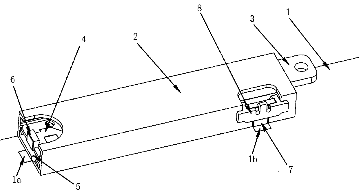
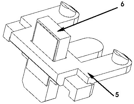
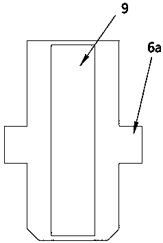
[0028] Referring to the drawings, a feed structure of a dielectric phase shifter. The dielectric phase shifter includes a bottom PCB feeder network 1 and a phase shifter cavity 2. The phase shifter dielectric plate 3 is installed in the phase shifter cavity 2 And the dielectric phase shifter PCB board 4, the phase shifter cavity 2 is provided with two notches corresponding to the input and output ports of the dielectric phase shifter PCB 4 respectively. One of the two notches is located in the phase shifter One end of the cavity 2 corresponds to the input port of the dielectric phase shifter PCB board 4, and the other gap is located at the other end of the phase shifter cavity 2, and corresponds to the output port of the dielectric phase shifter PCB board 4 . The feeding structure includes a f...


PUM


Abstract

The invention relates to a feed structure of a dielectric phase shifter. The dielectric phase shifter comprises a bottom plate PCB feed network and a phase shifter cavity. A dielectric phase shifter PCB is installed in the phase shifter cavity. The phase shifter cavity is provided with two gaps which respectively correspond to the input port and the output port of the dielectric phase shifter PCB.The feed structure comprises feed PCBs arranged at the positions of the two gaps; the front sides and the back sides of the feed PCBs are plated with copper, one side of the plated copper is connected with the bottom board PCB feed network to be grounded, the other side of the plated copper is connected with the dielectric phase shifter PCB to transmit signals; and the feed structure further comprises fixed buckles, wherein the fixed buckles are used for positioning and connecting the feed PCBs at the positions of the gaps and the dielectric phase shifter PCB and the phase shifter cavity. ThePCB insertion mode is adopted to replace cable feeding, SMT production can be achieved, the productivity is greatly improved, and the requirements for miniaturization, easy installation and batch production of the 5G antenna are met.

Description

Technical field [0001] The invention belongs to the field of dielectric phase shifters, and particularly relates to a feed structure of a dielectric phase shifter. Background technique [0002] With the advent of 5G communications, massive mimo antennas have become the mainstream of 5G antennas, and electrical downtilt is also an important indicator of 5G antennas. The traditional 4G antenna phase shifter has a large antenna space, so the phase shifter feed is mostly welded on the cavity by a cable method, but for 5G antennas, due to space limitations, the antenna phase shifter can no longer be used like a 4G antenna Cable connection, so the feeding mode of the phase shifter of the conventional 4G antenna can no longer meet the needs of 5G antenna for miniaturization, easy installation, and batch size. Summary of the invention [0003] The purpose of the present invention is to provide a feed structure for a dielectric phase shifter, which adopts a PCB insert method instead of ca...

Claims


Application Information

Patent Timeline
Patent Type & Authority Applications(China)
IPC IPC(8): H01P1/18
CPCH01P1/18
Inventor 方铁勇韦图双王鹏赵伟
Owner TONGYU COMM INC
Why Eureka
Try Eureka