electrical connector

A technology of electrical connectors and connectors, applied in the field of electrical connectors, can solve problems such as small dielectric constant, inability to meet matching impedance, and large inductive reactance

Active Publication Date: 2021-06-18
DEYI PRECISION ELECTRONIC IND CO LTD PANYU
View PDF3 Cites 0 Cited by
  • Summary
  • Abstract
  • Description
  • Claims
  • Application Information

AI Technical Summary

Problems solved by technology

[0004] In order to facilitate the assembly of the terminals, the accommodating grooves are relatively large, so that a large space around the terminals is filled with air, the dielectric constant around the signal terminals is small, and the signal terminals It is a slender structure, its inductive reactance is relatively large, and its capacitive reactance is small, so it cannot meet the matching impedance required for the signal terminal to transmit high-frequency signals

Method used


Image

  • electrical connector
  • electrical connector
  • electrical connector

Examples


Embodiment Construction

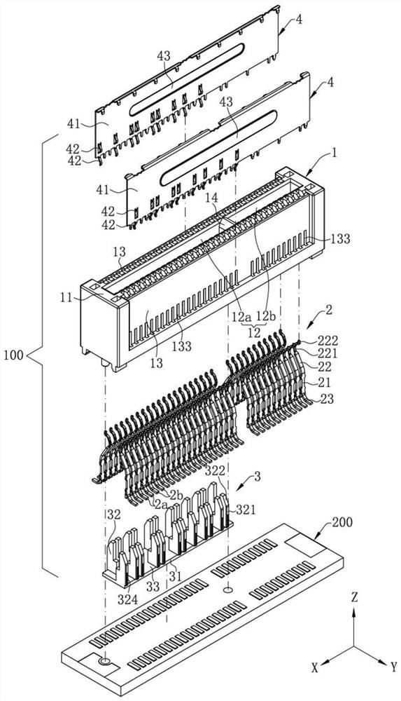
[0052] In order to facilitate a better understanding of the purpose, structure, features and effects of the present invention, etc., the present invention will be further described in conjunction with the accompanying drawings and specific embodiments.

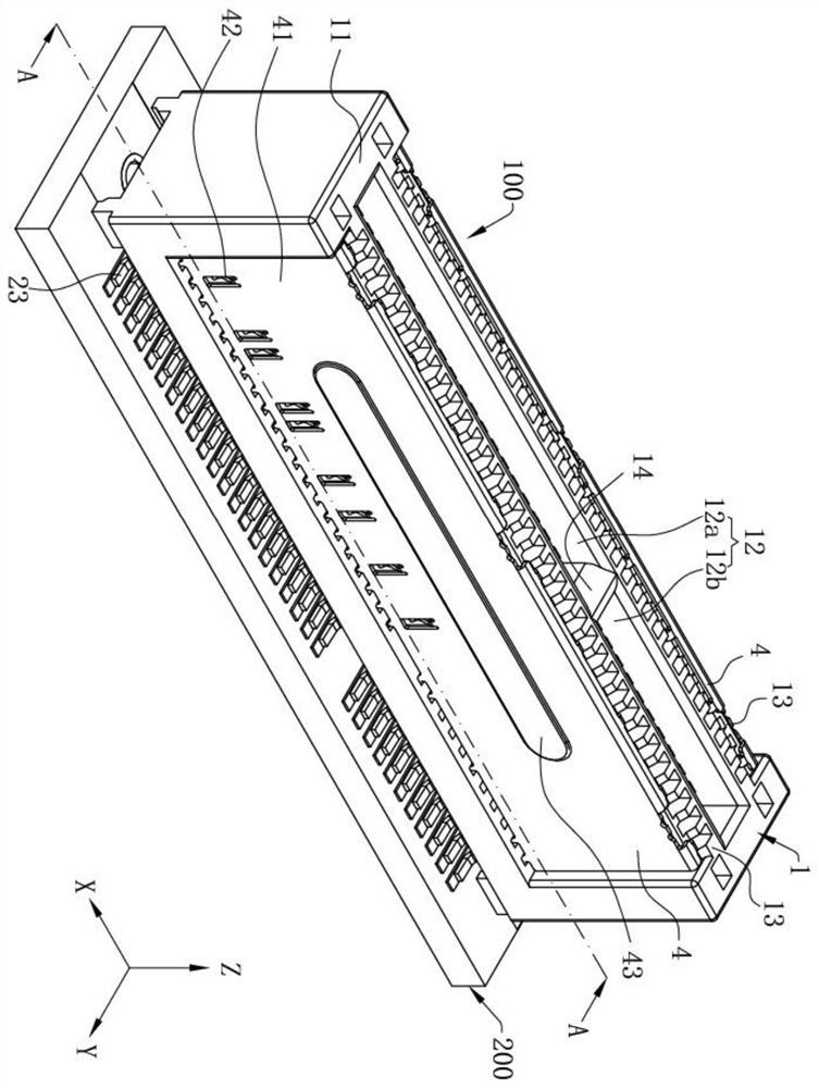
[0053] like figure 1 , Figure 5 and Image 6 Shown is the electrical connector 100 of the present invention, the electrical connector 100 is installed on a circuit board 200, and is used for inserting a pair of connectors 300, for example, the connector 300 is an electronic card. In order to facilitate the description of the specific structure in the electrical connector 100, a longitudinal direction X, a left-right direction Y, and a front-rear direction Z are defined, and the longitudinal direction X, the left-right direction Y, and the front-rear direction Z Two of them are perpendicular to each other. In this embodiment, the electrical connector 100 is installed on the circuit board 200 backward.

[0054] like figure ...


PUM


Abstract

The invention discloses an electrical connector, comprising: an insulating body, having a butt joint surface, a slot recessed from the butt joint face, and two side walls located on both sides of the slot, forming a bottom surface of the slot in the recess direction of the slot, One of the side walls is provided with at least one grounding receiving groove and at least one signal receiving groove; a plurality of terminals are arranged on at least one side wall, and the terminals have contact parts protruding into the slots, and the plurality of terminals include at least one signal terminal and at least one grounding Terminals, signal terminals are correspondingly stored in the signal storage slot, ground terminals are correspondingly stored in the ground storage slot; the insulating plug is installed in the insulating body, and the same side of the insulating plug is provided with a first part corresponding to the signal storage slot and corresponding to the ground storage slot. The second part, the first part is accommodated in the signal receiving groove and is closer to the mating surface than the second part and the bottom surface of the groove. In this way, the dielectric constant around the signal terminals can be increased, and the impedance of the signal terminals can be adjusted, which is beneficial to the transmission of high-frequency signals.

Description

【Technical field】 [0001] The present invention relates to an electrical connector, in particular to an electrical connector suitable for transmitting high-frequency signals. 【Background technique】 [0002] With the development of electronic science and technology today, electrical connectors have played an important role in the field of electronic technology, and the speed of information transmission is getting faster and faster, so the requirements for electrical connectors are getting higher and higher, not only electrical connectors Components can support fast transmission rates and also need to improve the stability of electrical connector signal transmission. [0003] A known electrical connector is used to electrically connect a mating piece, which includes an insulating body and a plurality of terminals arranged on the insulating body, and the insulating body has a slot for inserting the As for the butt joint, the slot is recessed from the top surface of the insulati...

Claims


Application Information

Patent Timeline
Patent Type & Authority Patents(China)
IPC IPC(8): H01R13/40H01R13/502H01R13/627H01R13/629H01R13/6477H01R13/652
CPCH01R13/40H01R13/502H01R13/652H01R13/627H01R13/629H01R13/6477H01R12/737H01R13/11H01R13/6597H01R12/716H01R13/64H01R13/6581
Inventor 张标殷佳旭梁崇成张文昌
Owner DEYI PRECISION ELECTRONIC IND CO LTD PANYU
Why Eureka
Try Eureka