A multi-channel bidirectional buck-boost circuit

A buck-boost circuit, multi-channel technology, applied in the direction of electrical components, adjusting electrical variables, high-efficiency power electronic conversion, etc., can solve the problems of high power consumption, complicated circuit design, etc., and achieve low total power consumption and simple circuit structure Effect

Active Publication Date: 2021-01-29
施耐德电气(中国)有限公司
View PDF8 Cites 0 Cited by
  • Summary
  • Abstract
  • Description
  • Claims
  • Application Information

AI Technical Summary

Problems solved by technology

[0002] To implement a multi-channel buck-boost conversion circuit, if traditional MOSFETs or IGBTs are used, they have the disadvantages of complex circuit design and high power consumption

Method used


Image

  • A multi-channel bidirectional buck-boost circuit
  • A multi-channel bidirectional buck-boost circuit
  • A multi-channel bidirectional buck-boost circuit

Examples


Embodiment Construction

[0044] The following will clearly and completely describe the technical solutions in the embodiments of the present invention with reference to the accompanying drawings in the embodiments of the present invention. Obviously, the described embodiments are only some, not all, embodiments of the present invention. Based on the embodiments of the present invention, all other embodiments obtained by persons of ordinary skill in the art without making creative efforts belong to the protection scope of the present invention.

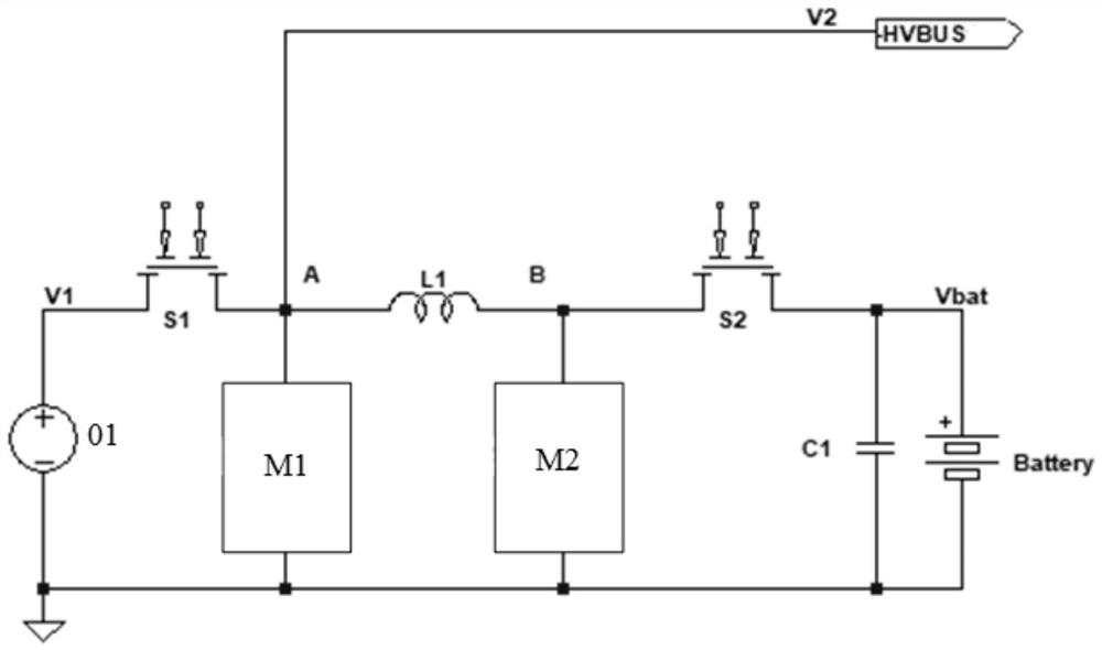
[0045] Aiming at the problems in the prior art that the design of the multi-channel buck-boost conversion circuit is complex and the working efficiency is low, the present application discloses a multi-channel bidirectional buck-boost circuit, see figure 1 , the circuit consists of:

[0046] DC power supply 01, the type of the DC power supply 01 can be selected according to user needs, for example, it can be a DC power supply such as AC-DC or DC-DC;

[0047] ...


PUM


Abstract

The present invention provides a multi-channel bidirectional buck-boost circuit. By controlling the gate drive timing of each wide-bandgap semiconductor bidirectional switch, the free transmission of electric energy between multiple channels is realized, that is, at different times, the power supply can be changed to The load that accepts electric energy can also become a power supply. For example, when the energy storage device is charged, it is used as a load, and when it is discharged, it is used as a power supply. This scheme uses a wide bandgap semiconductor bidirectional switch to control the circuit. Compared with the control method of MOSFET or IGBT in the prior art, the circuit structure is simple and the total power consumption is lower.

Description

technical field [0001] The invention relates to the technical field of integrated circuits, in particular to a multi-channel bidirectional buck-boost circuit. Background technique [0002] To implement a multi-channel buck-boost conversion circuit, if a traditional MOSFET or IGBT is used, it has the disadvantages of complex circuit design and high power consumption. Contents of the invention [0003] In view of this, an embodiment of the present invention provides a multi-channel bidirectional buck-boost circuit to provide a multi-channel bidirectional buck-boost circuit with simple structure and low power consumption. [0004] In order to achieve the above purpose, embodiments of the present invention provide the following technical solutions: [0005] A multi-channel bidirectional buck-boost circuit, comprising: [0006] DC power supply; [0007] A first wide bandgap semiconductor bidirectional switch, the first terminal of the first wide bandgap semiconductor bidirec...

Claims


Application Information

Patent Timeline
Patent Type & Authority Patents(China)
IPC IPC(8): H02M3/158
CPCH02M3/1582Y02B70/10
Inventor 李波
Owner 施耐德电气(中国)有限公司
Why Eureka
Try Eureka