Variable gain amplifier circuit

A gain amplifier and circuit technology, applied in gain control, amplification control, electrical components, etc., can solve the problems of deteriorating the quality of the received signal and increasing the bit error rate of the signal at the receiving end.

Pending Publication Date: 2020-04-10
ETOWNIP MICROELECTRONICS BEIJING CO LTD
View PDF1 Cites 0 Cited by
  • Summary
  • Abstract
  • Description
  • Claims
  • Application Information

AI Technical Summary

Problems solved by technology

This gain peaking will introduce non-linearity, deteriorate the quality of the recei

Method used


Image

  • Variable gain amplifier circuit
  • Variable gain amplifier circuit
  • Variable gain amplifier circuit

Examples


Embodiment Construction

[0078] The present invention will be further described below in conjunction with the accompanying drawings and embodiments.

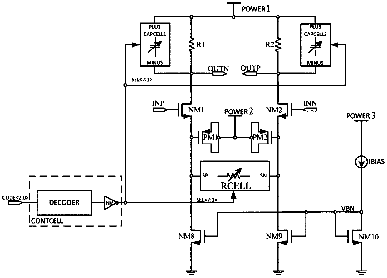
[0079] A variable gain amplifier circuit proposed by the present invention can select 2 N Gain levels, in a specific embodiment, a 3-bit control signal is used to realize 8-level gain control for illustration.

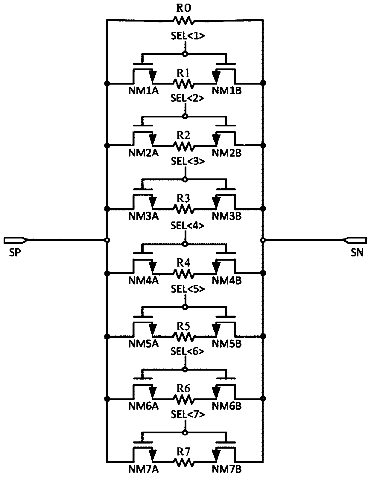
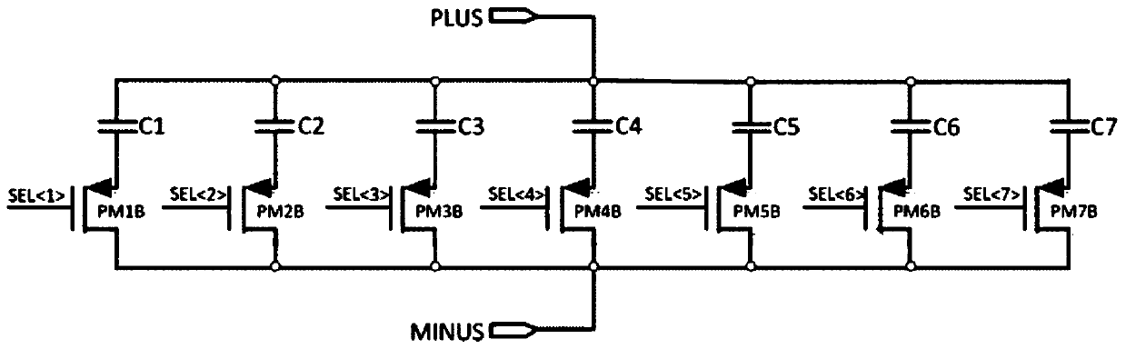
[0080] Such as figure 1 As shown, the input differential signal ports of a variable gain amplifier circuit proposed by the present invention are the differential signal input terminal INP and the differential signal input terminal INN, and the output differential signal ports are the differential signal output terminal OUTP and the differential signal output terminal OUTN. Using a differential CML (CurrentModeLogic) structure with source degenerate resistance and source degenerate capacitance, by selecting the output resistance value of the source degenerate resistance array RCELL (R S ), the transconductance of input differential pair NM1 an...


PUM


Abstract

The invention belongs to the technical field of integrated circuits, and particularly relates to a variable gain amplifier circuit which can be applied to a high-speed serial interface receiving end analog front-end circuit, provide multi-gear uniform adjustable gain within an input signal frequency range, ensure the linearity of received signals and improve the quality of the received signals. According to the circuit, a source end degenerate resistor array RCELL, a first load capacitor array CAPCELL1 and a second load capacitor array CAPCELL2 are controlled at the same time, a zero point introduced by a source end degenerate resistor and a pole introduced by a load capacitor array are counteracted, and peaking of a gain curve is avoided; 2N-gear gain is selected through N-bit control signals, a signal amplitude detection circuit and a digital control circuit are used in cooperation, and automatic gain control can be achieved according to the amplitude of input signals.

Description

technical field [0001] The invention belongs to the technical field of integrated circuits, in particular to a variable gain amplifier circuit applied to an analog front-end circuit of a receiving end of a high-speed serial interface. Background technique [0002] The analog front-end circuit at the receiving end of the high-speed serial interface needs to perform termination, equalization, amplification, calibration, detection and other processing on the input signal, such as Figure 4 As shown, the analog front-end circuit at the receiving end of the high-speed serial interface generally includes a terminal circuit, an equalizer circuit and a variable gain amplifier circuit. The variable gain amplifier circuit needs to provide multiple adjustable gains, which can be adjusted according to the input signal amplitude to ensure the linearity of the entire analog front-end circuit and avoid the introduction of bit error rate (BER) due to signal nonlinearity. In addition, since ...

Claims


Application Information

Patent Timeline
IPC IPC(8): H03G3/20
CPCH03G3/20
Inventor 徐震唐重林吴汉明
Owner ETOWNIP MICROELECTRONICS BEIJING CO LTD
Why Eureka
Try Eureka